Leaderboard
Popular Content
Showing content with the highest reputation on 10/17/2018 in all areas
-
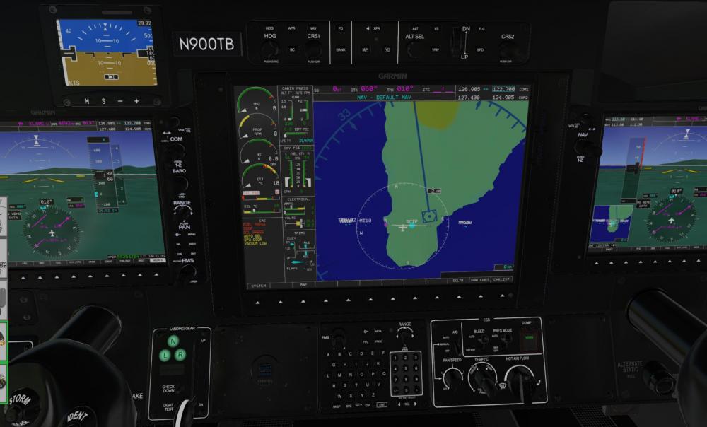
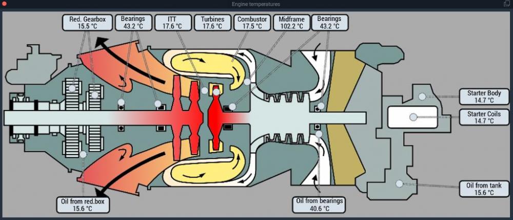
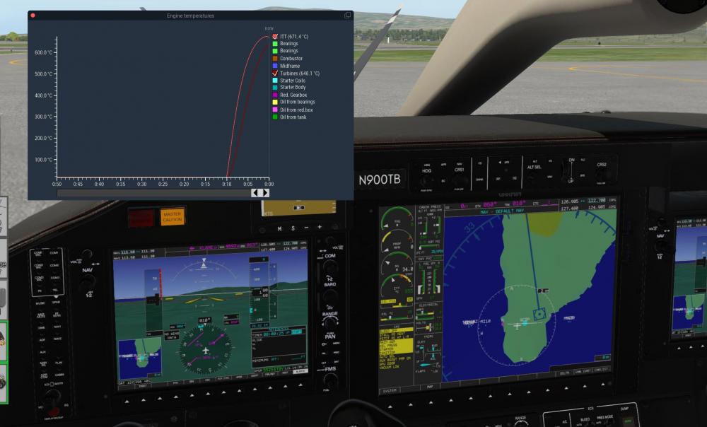
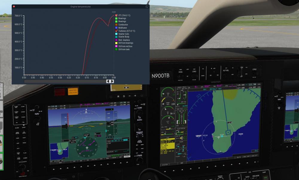
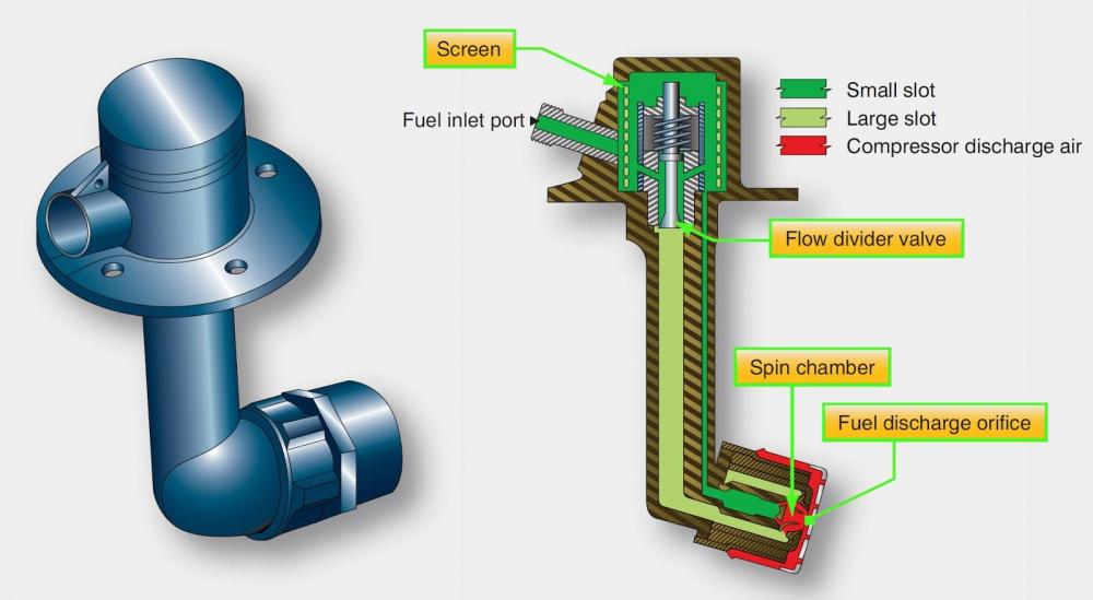
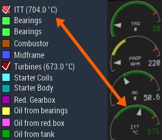
Captains, After more than one year of full time development I am pleased to announce the TBM-900 is on short final and will be ready for your hangars this weekend! Releasing Saturday at Midnight Eastern Standard Time (get ready to hit that buy button Friday night!). The TBM-900 is the most complex turboprop aircraft simulation produced for X-Plane to date, and one of the most interactive of all aircraft ever produced up till now. We truly believe this will make for a very exciting experience as you fly through the skies! Because of the complexities of the aircraft, and the fact that text is not always the most fun way to digest information, we will be doing a daily 1 hour livestream video session. Each day we will announce which time it starts, with the first one starting in just a few short hours today at 6:30 pm EST (2230 Zulu). You can watch the livestream by clicking here! (Previously Recorded) A brief run down of the core feature list is here: Heavily multi-threaded systems architecture to leverage performance of modern CPUs with many cores. Flight model tuned to perform to within a few percent of the real aircraft in the normal flight envelope, including maximum and stall speeds, rate of climb, fuel burn, trim behavior and control feel. Full aircraft state persistence. Every switch, flight control position, fuel state and on-airport position is restored upon reload. Even between reloads, system resources change in real time. The engine and oil cools down slowly between flights, the battery drains, tires slowly deflate, etc. Fine-grained systems model, down to individual sub-components. The always-on failure system realistically responds to wear & tear and overstress for each sub-component based on individual load factors. Over-torque, over-temp, frequent starts, hard landings, operating in FOD-contaminated environments and many more all affect individual sub-component wear & tear and service life. Sub-component wear realistically reflects on aircraft performance. Worn engine parts reduce maximum available power, worn prop reduces top speed, worn tires result in worse grip during ground ops, etc. Aircraft maintenance manager to inspect and repair or replace any damaged sub-component. The maintenance manager tracks per-airframe operating expenses in a realistic manner to show the real cost of operating the aircraft. Airframe manager that allows you to operate multiple simulated airframes, each with their own independently tracked wear & tear, livery selections and custom registration marks applied. Airframes can be automatically synchronized between multiple machines over the network with just a few clicks. This automatically syncs up aircraft position, configuration and wear & tear to simulate multiple users sharing the same physical aircraft. See how your fellow pilots treated the aircraft by checking the maintenance manager and engine trend monitoring outputs. X-Plane 11 G1000 avionics stack with lots of customizations and overlays to simulate the special extensions in the real TBM900. This includes a custom EICAS, systems synoptic pages and special integration with the extra simulated systems such as the weather radar, TAS, electrics, etc. Integrated Synthetic Vision into the PFD with obstacle display, navigation pathways, airport labels and TAWS-B integration. Integrated live charts display from FAA and Autorouter.aero. Navigraph integration will be available in a future update. Fully custom electrical system. Simulation of all buses, switching behaviors and reconfigurations. Full circuit breaker system, integrated with the X-Plane failure system, so a failed or failing system can pop a breaker. Highly accurate PT6 engine model with realistic startup and operating behavior. Engine lag, secondary fuel flow, ITT evolution, response to auxiliary load and many more fine-grained behaviors. Custom prop governor, with all modes simulated, including electric auto-feather with negative torque sensing. Crew Alerting System integrated into the avionics stack with all annunciations, takeoff/landing inhibits, flight state filters and "corner cases" simulated. Environmental Control System integrated into the custom EICAS. Air conditioning and pressurization respond in real time to environmental factors such as ambient temperature, pressure, available engine bleed air, cabin temperature setting, cabin pressure vessel failures, etc. Custom TAWS-B ground proximity warning system with all annunciations modes, inhibits, real-time impact point prediction and terrain painting up on the MFD to ranges of 200NM. The TAWS-B uses the X-Plane terrain DSF data to construct its database, so it is always "up to date". GWX 70 weather radar with weather & ground modes and realistic radar return painting. Full simulation of radar beam energy dissipation, signal attenuation when passing through dense weather and vertical cell analysis modes. Terrain mapping accurately paints surface features, including recognizable peaks, valleys and lakes. Supports the X-Plane 11 default atmospheric model as well as xEnviro. GTS 820 Traffic Advisory System (TAS) with aural alerts + visual alerts, the TAS MFD page and compatibility with X-Plane default traffic, PilotEdge, Vatsim and IVAO. Full simulation of the ESI-2000 standby instrument, including all configuration pages, sensor failures, AHRS drift and "roll-over" during extreme maneuvers, realistic battery operation and real-time battery depletion, etc. Dynamic custom registration mark paiting on the fuselage and instrument panel with support for custom TrueType fonts, colors and positioning. This lets livery painters make a "generic" livery and each pilot apply their own custom registration mark with just the click of a button directly in the simulator. Liveries can specify a custom position and font to optimize the look. Custom sound engine with samples from the real aircraft and accurate modeling of individual engine states and sub-component noises such as fuel pumps, gear pumps, flap actuators, etc. Now, let's roll onto our first day of systems overview briefs we will be doing up till release day! From the start, we have been focusing on making the aircraft "feel" like a real machine. And if you have dealt with real aircraft, you will know that they can be moody at times. Sometimes the engine starts on the first try, sometimes it just seems to want to drag its feet. Other times, you come up to the aircraft and the battery is strangely low, so you need to sit on the ramp after engine start a bit longer to let it charge up. While working on the core systems model in the TBM900, we have taken a great deal of time to focus on getting this kind "personality" coded into the aircraft. Looking at the above image, a watchful eye can immediately see that the "ITT" display is reading 18 degrees C. But the outside air temperature is just 15 degrees C. That slight discrepancy can be due to a number of factors. It could be a sensor inaccuracy. Or it might be some residual heat from a previous engine run. To provide such minute effects, under the hood the systems simulation actually breaks the engine up into tiny pieces and models heat flow between them. Normally those kinds of details would be inaccessible to the end user, but we have decided to go in the opposite direction. We will not only let you see the system details, we have built-in analysis tools for you to examine systems behavior in real time. All of the fields you see above are clickable and can be displayed like a graph of the last 10 minutes. While flying aircraft, we tend to forget about all the complexity that happens behind the scenes. We push a button and things just happen. But with the analytics screens built into our model, you can get an appreciation of what goes on inside the machine to make things go. Let's go for an engine start. We will skip most of the boring part of the engine start, that is the initial motoring and come right after fuel introduction. You can see that the engine has passed its critical "hot" point around 30% NG, but to help you visualize the engine model, I have brough up the ITT and Turbine temperature graphs. You can immediately see how the turbine temperature lags behind the ITT. That's because the ITT is the temperature of the exhaust gasses, while the turbines themselves contain quite a bit of mass of metal that needs to be heated. As the engine accelerates, you will see a double ITT spike that is very characteristic of the PT6 engine. No other aircraft model that we're aware of reproduces this correctly. The second ITT spike comes because the engine start is actually performed in two steps. The full fuel flow required to start the engine and bring it up to its low idle condition is too great at the low engine speeds. It would simply cause excessive engine temperatures during starting, which would significantly shorten component lifespan. So instead, the PT6 (and many other turbine engines) contains "duplex fuel nozzles". As you can see the fuel nozzle has two circuits, a small primary (darker green) and a larger secondary (lighter green). The primary is rigged with a flow divider valve that is spring-loaded to actuate above a certain fuel pressure. This is calibrated so that once the engine reaches 42% NG, the fuel pressure exceeds the spring tension and opens up the second fuel port and allows more fuel into the engine. In the TBM this manifests as a sudden rise in fuel flow from approximately 18 gallons per hour to 25 gallons per hour. There is also an audible rise in engine acceleration. The observant among you will also no doubt have noticed that the ITT display on the EICAS (Engine Indication and Crew Alerting System) is different from the graph value. The reason for that is rather simple if you think about how real sensors work. The sensor surface itself is a metal stud inserted into the gas flow. As such, it too takes a bit to warm up to the real gas flow temperature. In addition, the sensor is an analog device. There is an analog-to-digital conversion circuit that samples the sensor reading and since real sensor data contains some noise, the sample does input "filtering". In simple terms, it doesn't show the immediate value from the sensor, but instead gradually "filters in" the value sampled into an old reading. This provides output smoothing and a much more stable output value. So always keep in mind that what the aircraft's sensors are showing is probably a couple of seconds old anyway. In the next post tomorrow, we will focus a bit more on avionics and some of the cool features we have developed in that department. Stay tuned, and we look forward to seeing you in the TBM filled skies this weekend!4 points
-
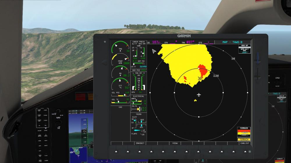
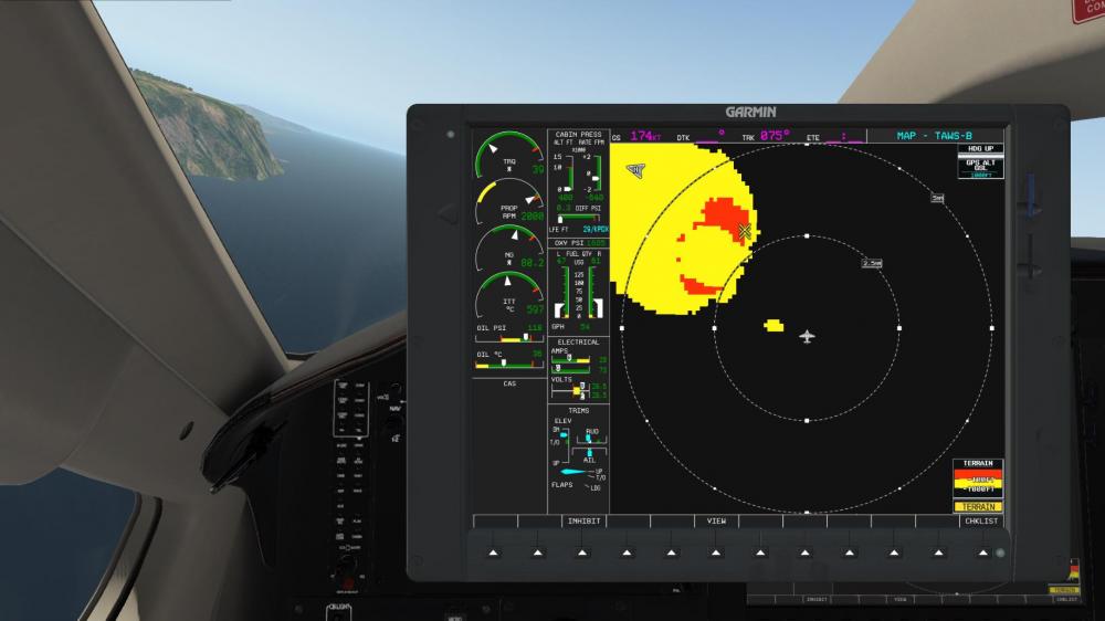
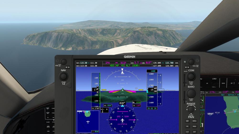
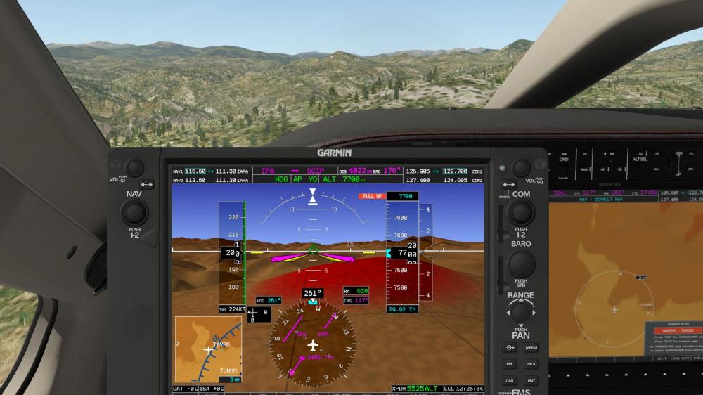
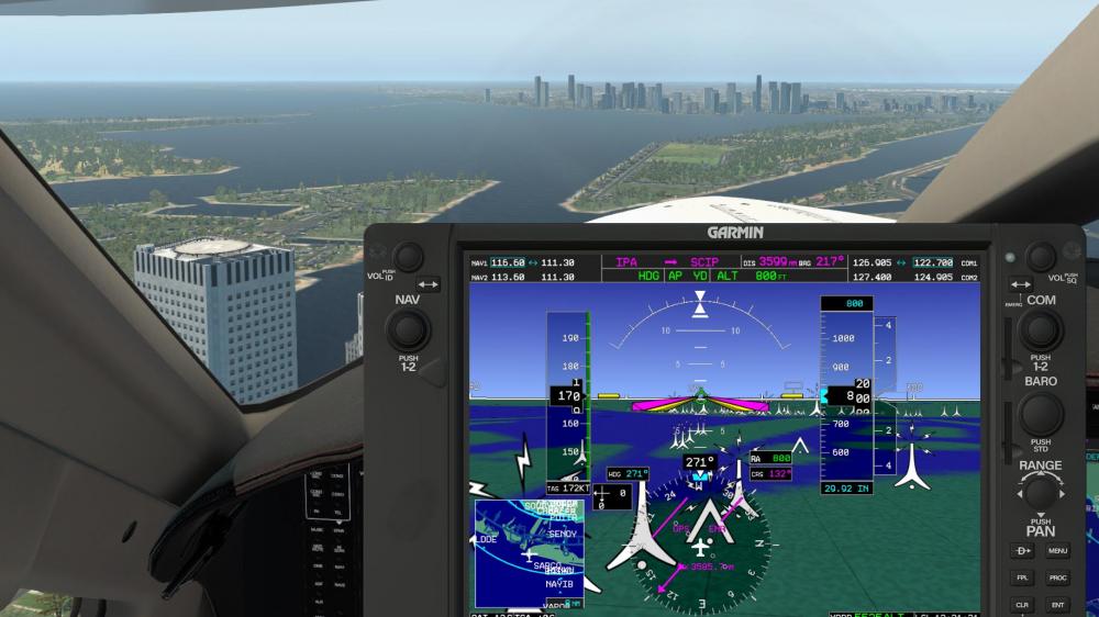
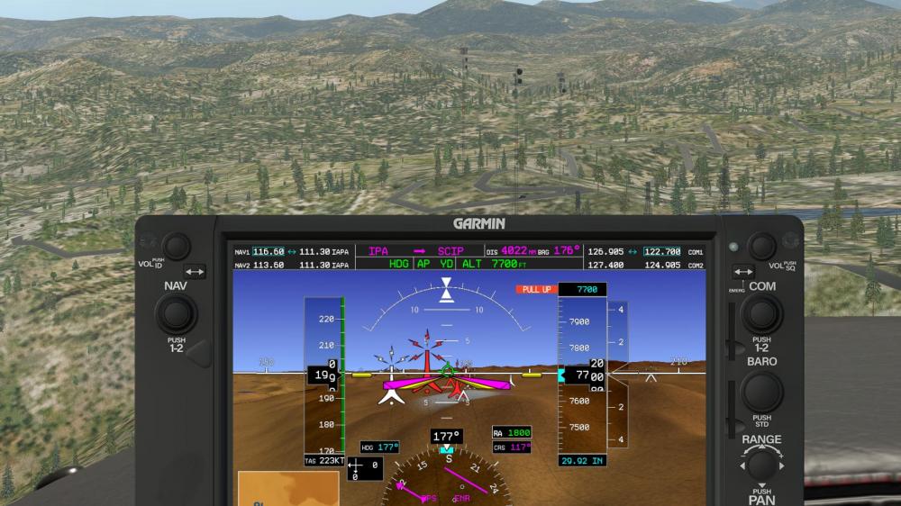
Captains, Continuing on with our release date announcement yesterday, today we are going to discuss Synthetic Vision & TAWS in our forum post, and avionics as a whole in today's livestream happening at 6:30pm EST (2230 Zulu). You can watch the livestream by clicking here! (Previously Recorded) And now, let's talk about the Synthetic Vision & TAWS! Modern avionics tends to place a lot of emphasis on visual cues to aid in situational awareness. A classic example that dates back to the late 80s is the terrain map displayed on the navigation display: Here you can see a reproduction of the Garmin TAWS-B (Terrain Awareness and Warning System - B). This system works in a rather simple manner. It contains a stored database of world-wide terrain, reads GPS inputs and projects the aircraft's flight path with turn, climb and descend trends to some future point (typically approximately one minute ahead). If it detects a potential terrain conflict, it will begin issuing aural cautions ("TERRAIN AHEAD"). If the pilot doesn't respond, the system will increase speaker volume and issue a hard warning ("TERRAIN AHEAD, PULL UP!"). In the following image you can see the path-prediction function. The aircraft is currently not headed in the direction of terrain, but it is turning towards it. The TAWS-B system detects this and shows the predicted impact point: The TAWS-B implementation in the HotStart TBM900 is designed to mimic the real TAWS-B in intimate detail, including all warning modes and realistic terrain resolution. To make terrain database updating a breeze, the aircraft doesn't actually use any internal terrain database. It reads the X-Plane DSF terrain files directly in a background thread to construct an always-up-to-date picture of the surrounding terrain. This system, while no doubt important and having prevented many a CFIT accident (Controlled Flight Into Terrain), with the proliferation of powerful graphics hardware in avionics since the late 2000s, more and more vendors have started adopting direct 3D terrain displays. One of the most sought-after incarnations of this technology is called synthetic vision: The HotStart TBM900 uses its terrain database information not only to display a classic TAWS-B screen, it also uses that same information to drive a real-time 3D display of the terrain around the aircraft. Although, strictly speaking, the simulator itself is already a synthetic kind of world. So should we be calling this "Synthetic Synthetic Vision" then? Regardless, the nice part of this feature is that the graphics hardware you have in your computer is so much more powerful than anything that aircraft avionics uses, that even though we have reproduced the real Garmin SVT system to near pixel perfection, your computer barely feels the weight. In our testing, the synthetic vision shows an almost negligible performance impact. And so if we have information terrain, path prediction and a 3D view of the world, what can we do with impact predictions? Quite simple: we just paint the hills in front of you with the appropriate color to warn you of impending doom. With the ability to draw arbitrary 3D graphics on the instruments, why not add obstacles as well? Although obstale databases are sometimes hard to come by, the US FAA publishes theirs directly on the web, free of charge. So when we detect that the aircraft is flying in a US territory, the avionics connect to the FAA's servers in the background and download the latest obstacle data file (once every 28 days). With this data in hand, we can show to an adventurous pilot when danger looms ahead, even if it isn't made of dirt: And this of course combines with the path prediction system again to produce obstacle impact predictions. While not that much of an issue in urbant areas, as there is plenty of light at night to indicate the presence of a city, this can come particularly in handy if some incosiderate person decided to build a lone radio mast right in your flight path. But of course, if for whatever reason you prefer not having the 3D terrain on the primary flight display you can turn it off. But should you want it for a quick peek anyway, feel free to just stick the terrain display onto a ForeFlight-like tablet onto the yoke (please note: this is NOT the full ForeFlight application, just a differently rendition of the TBM's 3D terrain display): This is just a few of the many integrated avionics systems that the aircraft boasts to aid you in your simulation endeavors. Of course, all this aircraft complexity demands some maintenance attention. Check back tomorrow when we will detail how to take care of your new aircraft and keep it performing to its fullest potential. We'll see you on the livestream (link at the top of this post) tonight for more in-depth conversation on the avionics!1 point
-
1 point
-
You can still see my big, freightened eyes in that picture! No worries, I have done worse in real life... Cheers, Jan1 point
-
1 point
-
While it is difficult to make exact estimates on framerates, an i7 4790K should be able to handle the aircraft avionics with ease. Most of the heavy lifting of the avionics rendering is shifted away to background threads, so even my piddly i5 4460 that I develop on was able to do a locked 60 fps while streaming yesterday. Of course, this was in an area with little scenery. I would say your performance will mostly be dictated by the scenery and your GPU horsepower, rather than being limited by the aircraft's systems code and CPU speed.1 point
-
I'm happy to assist others in writing one, but I don't plan on doing it myself. While I would consider shared-cockpit a core feature requirement for an airliner, the TBM is almost never flown multi-crew, so that puts the feature rather low on the priority list from a realism perspective. And a second reason is that the airplane runs tons of randomizing code that gives it the "organic" feel of every flight being different, every system responding a little different to inputs, etc. Replicating that between two nodes would be a major undertaking and I'm not really sure is even practically possible (at least to my requirement of stability & usability) by using smartcopilot's simple dataref syncing approach. I suspect it would take a much more integrated approach that would talk to the internals of the systems simulation directly.1 point
-
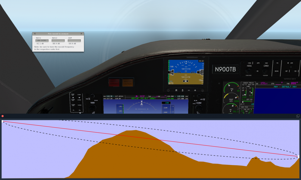
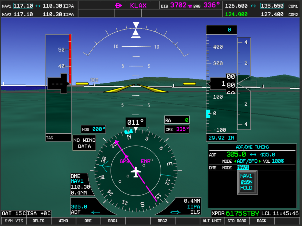
So as you fine folks may already know, in our usual style of going completely overboard on the level of detail, a few weeks back I've implemented a custom VHF radio signal propagation model. This means, NAV radios (VOR, LOC, GS and DME) are all simulating things such as terrain masking, terrain diffraction, tropospheric scattering, etc. The underlying computational model is based on the NTIA Irregular Terrain Model (ITM), an industry-standard model used for things like radio tower planning. The simulation includes a built-in analytics display that allows you to check the terrain profile being used by the radio model (please note, the image below isn't hand-painted, it updates in real time as you fly): What's recently new is that I re-implemented the ADF and standalone DME radios as well. So the entire radio complement in the TBM is as follows: Two VOR/LOC/DME radio. One ADF radio One standalone DME radio That involved re-implementing all course deviation needles and the DME tuning pages on the PFD. All features of the real G1000 are simulated, even some of the more odd ones: ADF, ANT, ADF/BFO and ANT/BFO reception modes. This is reflected in the audio ID portion, including the continuous tone you hear in BFO mode when no ADF signal is being received. All DME tuning modes simulated, so NAV1 slaved, NAV2 slaved and HOLD. Allows for flying the more bizarre approaches, such as NDB/DME. Intercom audio routing from the radios is properly implemented, so NAV1 & NAV2 buttons route the audio ID for the NAV1/2 VOR/LOC portion, the DME button routes the standalone DME radio audio (including 1250 Hz square-wave tone, instead of 1kHz sine wave) and the ADF radio routes the ADF radio audio (including proper tone & background noise behavior depending on reception mode).1 point


