Leaderboard


Popular Content
Showing content with the highest reputation on 01/22/2024 in all areas
-
Hi, I think the question is when one can download next CL650 update? something released after 1.71 point
-
https://forums.x-plane.org/index.php?/files/file/82888-flywithlua-ng-next-generation-plus-edition-for-x-plane-12-win-lin-mac/1 point
-
Is there a future that sees a full Turbo SR22T G1000 TN is not the same performance or numbers1 point
-
I'm one of this 1%!!! I'd like to do the maintenance, polytechnician-pilot! ;-) The very complaint I have with this fantastic addon is that my nights are very short since I have this beautiful bird. What you guys have done is just amazing, a step forward in Flight Simulation, definitely worth it! I'm speechless! Congratulations to the devs, the team, X-aviation and thank you for the joy!1 point
-
Hi all. I have made a LUA script that enables random failures for the Challenger 650. Check out the link below for more details:1 point
-
The ODP or SID is not intended for OEI terrain and obstacle clearance since the criteria does not consider both the actual takeoff flight path of the aircraft following an engine failure nor does the climb gradient on an ODP or SD account for all obstacles that much cleared to meet the operating rules. An ODP or SID provides obstacle clearance with all-engines-operating because that's what its criteria assumes. Make sense? With the proper obstacle information concerning obstacle height above the runway and distance from reference zero, the FMS calculator can be used to calculate OEI takeoff obstacle clearance in accordance with the operating rules. Here's an important caveat. You need the relevant terrain & obstacle data and collecting that data no small feat. There are multiple data sources that need to be consulted, which is why the airlines have performance engineering departments dedicated to that task. For the business aviation community, we have contract providers such Aircraft Performance Group, ASAP Inc., Aerodata (now owned by Garmin), and Jeppesen OpsData through ForeFlight that provide this type of engineering support, and provide takeoff performance/obstacle clearance data in the form of airport runway analysis. As real CL300/350 pilot, I would never attempt to gather the obstacle data from the various sources and use the FMS calculator, in the same way that I would never attempt collect obstacle data and build my own instrument approach procedure to a runway. The FAA is expert in building instrument flight procedures and these performance engineer providers are the experts in airplane performance and engine failure escape procedures. I was never really quite sure why the FMS manufacturers (OEMs) put the obstacle clearance routine in their FMS. It's not unique to Collins. It's in the Garmin 5000 as well. If you had one known obstacle that you wanted to clear, one that as not accounted for in your contractor-provided analysis, for example a temporary obstacle, then yes, I could see a use for it. Although in 18 years of flying Collins FMS equipped aircraft, I have never used it other than for experimentation and familiarization. Rich1 point
-
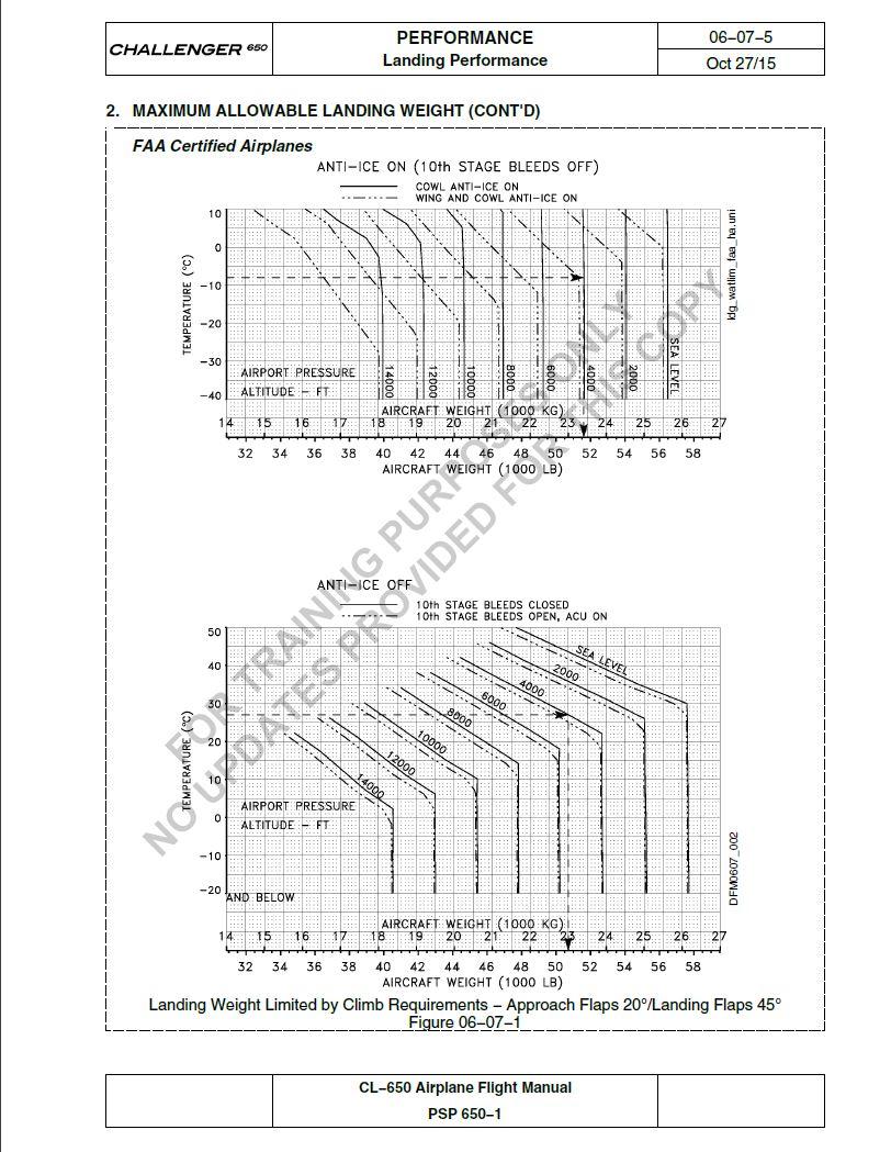
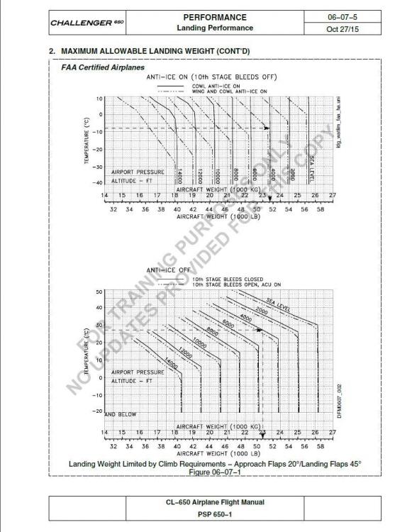
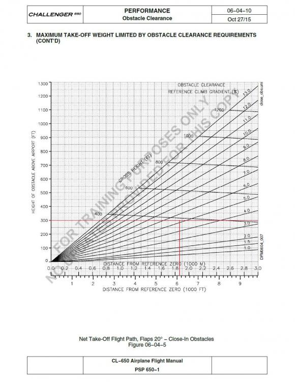
I neglected to answer your questions on approach climb and landing climb gradients, and what they are based on here. What we have in the FMS is a good hearted attempt to provide information to the pilot that is really relevant to performance. I'll explain in a moment. Approach climb is certification performance requirement. It is the climb gradient available with the aircraft in the approach configuration (flaps 20 for the CL65), landing gear retracted, with the thrust set to go-around thrust, a climb speed not more than 1.4 VSR (reference stall speed), and based on the published AFM procedures for a OEI go around. The minimum climb gradient is 2.1%. Landing climb is also a certification performance requirement. It is the climb gradient available in the landing configuration, landing gear extended, at VREF speed, and with thrust available 8 seconds after go-around thrust is selected (which may be less than the actual go-around thrust as the engine spools up). The minimum climb gradient is 3.2%. These two climb gradients are "certification requirements" and established as part of the maximum allowable landing weight for the aircraft in the AFM Limitations Section. For the CL650, they are published in the AFM Performance Section, but incorporated into the Limitations section by reference. The operating regulations for flying the airplane require that airplane's takeoff weight, less fuel and oil consumed in flight, allow the airplane to arrive at the destination airport and alternate airport (if applicable) at weight that is less than the maximum allowable landing where the approach climb and landing climb requirements are met. The AFM has an Approach and Landing Climb weight limit chart. That chart is incorporated into the FMS performance module. When you complete the APPROACH performance page, if you are overweight, for the information that you entered for landing, the FMS will tell you: MLW Maximum Landing Weight (MLW) is determined by the most restrictive selection among the following: structural limit weight, climb performance limit weight, and runway length limit weight. If MLW is unable to be computed, the MLW data field is blank. When landing weight is greater than maximum landing weight, the MLW shows in yellow. In addition, a CDU message CHECK APPROACH PERF shows under these conditions. MLW values are synchronized on the APPROACH REF pages All of the one-engine-inoperative (OEI) takeoff, OEI approach climb, and all-engines-operating (AEO) Landing climb gradient requirement are not true climb performance requirements. They are statements of excess energy available to the aircraft in the stated configuration, at the applicable speed, and with the available thrust. That excess energy can be used to climb the aircraft or accelerate it, as appropriate. Further, the climb gradient values are "spot gradients" that a valid only at particular point in takeoff or landing phase. For example, the 2nd segment climb gradient data and climb gradient value determined is only valid at the exact instant that the landing gear is fully retracted after takeoff at V2 speed, with the takeoff flaps, and with takeoff thrust with one engine inoperative. Once you leave that "spot", the climb gradient decrease. For 2nd segment, or reference climb gradient as Bombardier calls it, the decrement in climb gradient that occurs as the aircraft climbs is built into the two flight path charts that I posted earlier, and is why the takeoff flight path charts are used to determine obstacle clearance rather than computing a "rise over run" climb gradient requirement, e.g., 300' obstacle, 1 NM away, minimum climb gradient 300 ft/NM or 4.9%. That doesn't work out that way when you use the flight path charts for the reference climb gradient required for obstacle clearance. Using the flight path chart, the reference climb gradient required to clear a 300' obstacle 1 NM (6076 feet) from the runway end (assuming takeoff distance required is equal to the runway length) is 5.3% (see example). As long as your Maximum Landing Weight is not showing overweight in the FMS for the conditions you entered, follow the AFM go around procedures, and you will meet the performance requirements. For OEI go around, climb a speed not less than VAPP and for all engines missed approach, a speed not less than VREF. However, at most landing weights, you'll be well below these limits and the AFM procedure will likely result in speeds being attained above these limits at the recommended go-around pitch attitude. If that's the case, take the extra speed. Rich Boll
 1 point
 -
Just to clarify, a missed approach climb gradient and SID/Obstacle Departure Procedure ODP climb gradient are based on normal, all engines operating aircraft performance: https://www.faa.gov/other_visit/aviation_industry/airline_operators/airline_safety/info/all_infos/media/2018/InFO18014.pdf The approach (one engine inoperative’ and landing climb (all engines) gradients provided on the APPROACH REF page 3/4 are spot gradients at the airport pressure altitude and temperature. These climb gradients are certification requirements, but do provide a gouge on climb performance on a missed approach or rejected landing provided the missed approach climb is relatively short. I suspect this example, by the looks of the landing minima is a mountain airport. At such an airport, I would have the one engine inoperative departure procedure for that runway programed in the ALT LEGS page and ready to fly should I go missed or rejected landing and then have the engine fail. Rich1 point
.thumb.jpg.ede78836fe6795baf7b91e5eb2aad35e.jpg)