Leaderboard


Popular Content
Showing content with the highest reputation on 08/09/2012 in all areas
-
Chris and me know what this means ...1 point
-
Tom, Tom, Tom... first rule to learn as an aspiring airline pilot - when kids visit the cockpit (no offense, Meshboy! ;-) ) - ALWAYS turn on the "light test" for the "christmas tree show"! ;-) Jan
 1 point
 -
I have tried it, and it is a very beautiful scenery. I love the detail it has, specially on building and grass. There is an issue when loading it (with one of the textures I guess) although you can load the scenery normally. So many thanks! Wating for more from Slovenia. Regards,1 point
-
Universal FMC
 1 point
 -
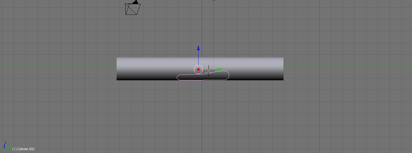
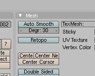
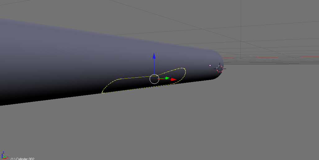
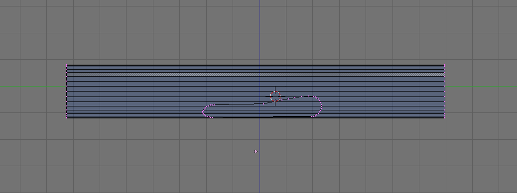
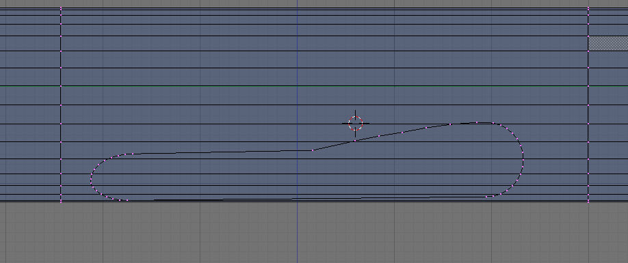
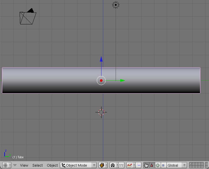
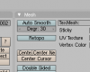
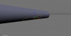
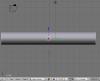
Hey all- I received a request to post a tutorial concerning how to build the wingbox on a obj fuselage. Like anything else, there are multiple ways to do this, and a number of nuances that will result in modifications to this procedure. So, take this as a basic guide, and be sure to critically analyze what your goal is. To begin, here we have a basic tube "fuse": You then switch to the side view (3), and create a separate object that is the outline of the wingbox root on the fuse. Note how many verticies you use for this, as you will need this number later. (makes things easier) Now, you go down to the menu on the bottom (in edit mode with the outline selected) and hit the retopo button. BE SURE TO BE LOOKING AT THE SIDE YOU WANT TO PROJECT THIS OUTLINE ON TO! Then, simply hit "G". The outline should snap to the contour of the fuse, and you'll get something like this: ***Before doing ANYTHING else, be sure to deselect the retopo button. Then, select the contoured outline and the fuse objects in object mode, and press ctrl-j to combine the objects. It should look like this: We then use the kinfe tool ("k") and create vertex loops at the boundaries of the wingbox outline, producing this: Next, erase the faces occupying the space inside of the outline, to make it look like this: This should be more than enough to occupy your time for now, and I'm tired, so this tutorial will be continued tomorrow...If you cannot wait, here are the rest of the steps w/o pictures: 8) Continue using the 'k' tool to create vertex loops for all of the verts on the top and bottom of the outline, so that the outline is now fully attached to the fuse. 9) At each end, strategically creat polys to join it to the original boundary vertex loops created in step 6. 10) Go to the side view again (3), and create another outline of the wing root, and space it appropriately in distance from the fuse. This outline should be composed of the same number of verts as the wingbox outline. 11) Strategically use the "k" tool to divide the new face loop into workable sections. For complicated curves in the wingbox (like on the 757), you should need 3-4 longitudinal loops. Less or more depending on the complexity of the curves. 12) Use ctrl-E-->edge slide to adjust their latitudinal position appropriately (left and right when looking from the nose back) 13) Contour/scale each longitudinal loop to create the appropriate contour and shape for your wingbox. ***Note: It's best to use/model only half a fuselage until after this step. Once complete, you can simply use the mirror modifier to duplicate this to the other side.


 1 point
 -
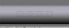
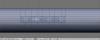
Okay so you've built your pretty little fuse, but you now are faced with the challenge of cutting holes in the tube. Simple enough, right? That's why you have boolean...WRONG! If you use Boolean tools, you're going to be left with a freaking disaster. So, here's the right way to do it. To do this properly, you begin with your fuse in the side view: Now, using your backround image as a reference (not used in this tutorial, obviously) create the shape of a window, as a separate object. Once you've gotten the shape right, hit Ctrl-D to duplicate, and without clicking etc, press y (or whatever your longitudinal axis is) and enter the value you would like to displace the second window. Repeat as necessary. It should produce something like this, with equidistant spacing between the windows: Next, you need to create a rectangle (same object as the windows) around ALL the windows, deleting the face only, and then subdividing appropriately. I always try to insure that the circle has verticies which are lined up along the vertical and horizonal axis. If you do this properly, there should be a pair of vertical verticies for each window (top and bottom) and a pair of horizontal verticies (left and right). Now, everywhere along the top and bottom edges, you want to subdivide so you have a vertex. Selecting the top and bottom edges of the box, hit Ctrl-W-->Subdivide multi and enter the number of cuts you want the program to make (in this case, 7). Repeat for the horizontal edges. Note: Because I used perfect circles for my windows, I only have one horizontal vertex pair to deal with. Those who are doing long, oval windows, may want to consider 2. Use some judgement here, as you will have to mate these verticies with the existing lines on the fuse down the road. Anyway, so if you didn't screw it up, it should look like this: And when you fill everything in: Here's where things get tricky. Remaining in the side view and in edit mode, select all verticies in the object. (its MANDATORY that you are facing straight at the objects you want to overlay. If you are at the wrong angle, since Blender retopo's from view, and not object orientation, it will project the object along a straight view path.) Then, once you're sure your projection will be correct, hit the retopo button... ...and press "G". The windows should snap to the topography of the fuselage. IMMEDIATELY DE-SELECT THE RETOPO BUTTON! If you're still with me, it will look like this: If it does indeed look like the above image, in object mode, select the fuse and window objects, and join them by pressing Ctrl-J. Going back to edit mode, you will see this: Now, you notice how none of the verticies of your windows are attached to the main fuse? To fix this, you're going to press Shift-S and click cursor to slection. Once the red and white deal snaps to the selected vertex, press the period key (this tells blender that all movements of verts are in relation to the one with the cursor on it). Starting from the first vertical vertex line, press "k" and add a vertex loop to your fuse. Once added, press "S", "Y (longitudinal axis), "0" (zero). Your vertex loop should snap to line up with the vertex with the cursor over it. Continue this process for all vertical vertex loops. NOTE: When using the knife tool (K), remember that you have to create the loop "downstream" of the first. Thus, if you go left to right, you create the next loop to the right of the first and so on. Once you have all the loops created, join the verticies of your "window box" to the verticies on the fuse. To do this, select the vertex on the fuse first, and the window box second, and press Alt-M-->Snap to first. If all is still going well, it should look like this: Also, you need to merge the horizontal verts as well. Do not create horizontal loops if you can avoid it. If you notice, in this tutorial, I simply merged the horizontal verts to the closest horizontal line on the fuse. Easy enough... WE'RE ALMOST THERE!!! Next, you want to go into face-select mode, and erase all of the faces that are behind your window box. If you merged the verticies properly, when you remove them, the only holes should be where the windows are, and it should resemble this: Now, you could stop here, but since we always want to get the most bang for your buck, you need to remove some verts by joining the edge loops at the middle line. If you do it correctly, the pattern should be Triangle, line, triangle, line, etc...See the image to get what I am talking about: So, if you have followed my caffinated ramblings, you should have something that looks like this:


 1 point