-
Posts
427 -
Joined
-
Last visited
-
Days Won
29
Content Type
Profiles
Forums
Latest X-Plane & Community News
Events
Downloads
Store
Everything posted by Graeme_77
-

14th stage bleed system - engine cowlings open the wing anti ice?
Graeme_77 replied to jantorre's topic in Systems and Tech
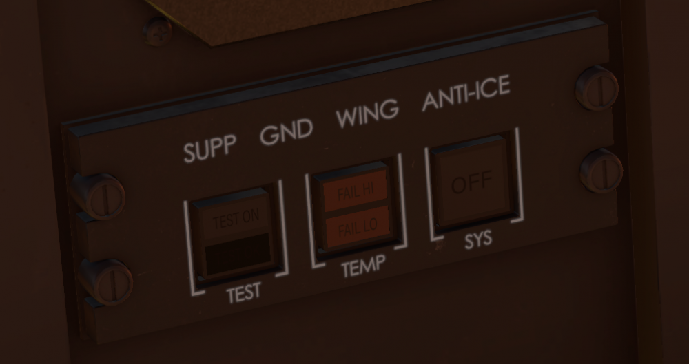
Yes indeed, that's the correct behaviour. Thanks for using the study menus to explore the Challenger 650, that's exactly what the developers hoped would happen! Challengers have a system called Supplemental Ground Wing Anti-Ice System. This was originally an option on the 605, standard equipment on the 650 and a possible retrofit for the 604. The system was made standard equipment after some suspected ice related incidents on the Challenger series. On the ground only, the use of cowl anti ice on both engines will feed bleed air to the wing system at a low temperature in order increase the ice protection on the wing. The system is disabled when takeoff power is applied and in flight, then the normal wing anti-ice system is the only way to open the wing anti-ice valves. This system is tested during the long 2 minute test in the after start checklist, but in normal operation the system is fully automatic. -
The 2D APU panel is not correct on the release version, but it is modelled and useable in 3D. Walk out the door, round to rear fuselage on the left side, open the access door, and reset the APU. The issue is usually caused by turning off the battery while the APU is running. Also here
-
I'm not rated on the 650, but I am A320 rated and current. There were also a group of CL650 rated (and flight sim experienced) pilots who tested the model extensively, as well as CRJ200 pilots on the testing team, and again they are flight sim experienced, not just somebody that spent a few minutes with the model. It doesn't seem too different from the Airbus and there was a fair bit of work carried out on the FD tuning during development. Here's a blind landing with the Flight Directors only after inducing a significant lateral and vertical disturbance at 1000ft. https://streamable.com/qq4nq7 I'll load the aircraft to LDDU to check, are you using stock scenery and Navigraph data? A video of the real thing too, showing FD behaviour
-
You've probably been conditioned to other sim products behaving in a simplified manner. The Flight Directors are not providing a simple "put the nose here and wings here" indication, but rather they help lead the pilot to the correct attitude. By that I mean that even if the FDs ultimately want 5 degrees nose up, the bar will not show on the 5 degree line, but rather the displacement of the bars from the index indicates the rate of change the pilot is expected to need. Big distance to the FDs? "Hey! Pay attention!" Little distance to the FDs? "You're doing fine, just a little nudge." Ultimately, it's just another tool for the pilot to use.
-
It is real behaviour. Verified by the type rated, current Challenger pilots Hot Start have been working with.
-
Hold brakes regular for the toe brakes - I use "B" Toggle brakes max effort for the parking brake - I use "V" You must hold the toe brakes, then set the parking brake, then you can release the toe brakes. So hold B, press V, release B.
-

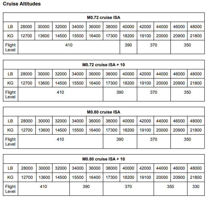
What are the optimal cruise FL for CL650? How to determine?
Graeme_77 replied to Gábor's topic in Flying the Challenger
-
Just to explain the issue clearly. In real life altimeters suffer from "errors". When it says 10000ft it doesn't mean you're 10000ft above the sea, it means in the conditions the altimeter was calibrated for, if the subscale (baro) was set perfectly, you'd be at 10000ft. On a cold day you could be at 9000 "real" ft, on a warm day 11000 "real" ft. But the altimeter would still show 10000ft. Now all real aircraft fly in the same real sky, so on a given day, one aircraft indicating 10000ft and another aircraft indicating 11000ft will pass each other safely. Even if their altimeters say 11000ft and 12000ft respectively. The Challenger 650 simulation includes these altimeter effects. Unfortunately when reading the information from X-Plane, online network clients read the "real" altitude (to draw the aircraft) and importantly (and unfortunately) show that to the controllers. This does not happen in real life, as controllers and transponders have no secret data from the world. This means online controllers will see an incorrect Flight Level reading when the Challenger 650 is doing an accurate simulation of real altimetry. To prevent any issues, the Challenger 650 simulation includes an option to disable accurate altimetry for flying on line. If you disconnect from the network, the Challenger will resume simulating altimetry effects, and as a result may climb or descend. It's the hope that in the future online networks will read two separate values, one "real" altitude to draw the various aircraft in the 3D world, and one "sensed" altitude, to downlink to controllers for the Transponder / SSR altitude. More information on altimeter errors https://skybrary.aero/articles/altimeter-temperature-error-correction
-
Personally I'd like to see them, but I don't know is the only answer I can give. It's probably quite far down the list of desired enhancements.
-
If you don't have custom recording, the checklist can do Text To Speech. Try the quick turnaround checklist to hear this.
-
L Mode S Transponder with ES B1 ADS-B Out via 1090 ES V1 ADS-B Out via VDL Mode 4 D1 ADS-C with FANS 1/A
-
The set of procedures the simulation has is not likely to be changed as the developers and SMEs felt the prescriptive nature of the read-and-do procedures would be of most use to sim pilots who enjoy flying loads of different aircraft types. However the system is open to user customisation and everybody is keen to see what VA, airline and military SOPs the community comes up with.
-
The CG value in the FMS Takeoff perf page is for pilot information only. It does not need to be completed, and has no effect on the performance of the aircraft. The developers are investigating options to display load and balance information in a manner that best simulates the corporate pilot experience as it differs substantially from scheduled air transport.
-
To add, if you want to use CRJ procedures, the checklist system is totally customisable, it's an XML file in the aircraft directory and is self explanatory. It was designed to allow users to create their own SOPs and procedures.
-
Your MCC instructor should have told you that everything in complex aircraft is done slowly and methodically ;-) It's not an airline memory/flow operation followed by the checks, these are read-and-do procedures for pilots that fly about 200 hours per year, sometimes less than 20 on type. We have subject matter experts testing the product, and these are real world procedures verified by pilots with extensive Challenger experience. V speed callouts are not implemented.
-
I hope so do, as do the developers - they're keen to fix it!
-
The simulation does not have windscreen ice effects at the moment - those effects must be coming from a plugin. We've had a look and the CL650 simulation could possibly be writing back some X-Plane default datarefs to help with that. Hopefully will be updated next release.
-
Yes, the SVS and Terrain require GNSS position source. Also Inmarsat antenna will not be able to track as it has a GNSS system feed to drive the active antenna, but you should be able to use Iridium for satellite data line.
-
You're welcome. For anybody else wondering what is actually being discussed here, it's the flightplan equipment codes that indicate the aircraft navigation and communication capabilities. M-SBDE1E2E3FGHIJ1J4J5J7M3RWXYZ/LB1V1D1 M Medium Wake Vortex Category S Standard Com / Nav Equipment B LPV SBAS D DME E1 FMC WPR ACARS E2 D-FIS ACARS E3 PDC ACARS F ADF G GNSS H HF Radio I Inertial Navigation J1 CPDLC ATM VDL Mode 2 J4 PDLC FANS 1/A Mode 2 J5 CPDLC FANS 1/A Inmarsat J7 CPDLC FANS 1/A Iridium M3 ATC RTF Iridium (Aircraft Number on FPL) R PBN Approved W RVSM Approved X MNPS Approved Y VHF 8.33 Channel Spacing Z Other Equipment L Mode S Transponder with ES B1 ADS-B Out via 1090 ES V1 ADS-B Out via VDL Mode 4 D1 ADS-C with FANS 1/A PBN/A1L1B1C1D1O1S2T1 A1 RNAV 10 (RNP 10) L1 RNP 4 B1 RNAV 5 all permitted sensors C1 RNAV 2 all permitted sensors D1 RNAV 1 all permitted sensors O1 Basic RNP 1 all permitted sensors S2 RNP APCH with BARO-VNAV T1 RNP AR APCH with RF (special authorization required) DAT/1FANSER2PDC 1: FANSER Primary: CPDLC-DCL and en route clearances. 2: PDC Secondary (will be used if primary is not available) SUR/260B Compliance with RTCA DO-260B (Minimum Operational Performance Standards for 1090 MHz Extended Squitter ADS-B and TIS-B RSP180 Aircraft is authorized for Required Surveillance Performance RSP180
-
You don't actually need to fly there, you can load it into the FMS at any point and calculate it. Calculating potential departure performance would be a useful use of cruise time. Just type in the runway length, temperature etc and you can grab the data via the FMS.
-
12556 kg in X-Plane includes the pilots. Operational Empty Weight or Basic Operational Weight. 12315 kg in the SimBrief profile does not include crew weight. Basic Empty Weight. Pax weights - 58kg - 81kg, with 6kg standard deviation, depending on geographic location Seasonal variation +/- 4 kgs Baggage - 15kg with 4kg deviation. Non-persistent mode gives you the aircraft with just two pilots. It is intended to bring a Study menu visualisation of the passenger distribution and other parameters to the aircraft in a future enhancement.
- 13 replies
-
- 10
-

-

-
DAT/1FANSER2PDC 1: FANSER Primary: CPDLC-DCL and en route clearances. 2: PDC Secondary (will be used if primary is not available) SUR/260B Compliance with RTCA DO-260B (Minimum Operational Performance Standards for 1090 MHz Extended Squitter Automatic Dependent Surveillance – Broadcast (ADS-B) and Traffic Information Services – Broadcast (TIS-B)) RSP180 Aircraft is authorized for Required Surveillance Performance RSP180
-
Conceptually the ATS is quite different from a 737 type of autothrottle. Let me try and explain it simply: The ATS will only work if there is a valid thrust rating. Click the PERF button on the CDU, and make sure it shows <ACT> next to a rating. You can use the TOGA buttons at any point, even on stand with the engines shut down, to arm the flight directors and ARM the autothrust system. It will then show "N1 TO" on the ATS matrix display. If the flight directors are already showing, you must turn them off and then press TOGA to arm the ATS. For takeoff, just push the power levers forward or press the "ATS" button on the FCP. This will then engage the ATS to give you takeoff thrust. If at any point you have FAIL on the matrix display, you must use the ATS Disconnect, (look for at_disc in the bindings) to clear the matrix display before reengaging the ATS. Hope that makes enough sense to get you going.


