CaptCrash
Members-
Posts
198 -
Joined
-
Last visited
-
Days Won
4
Content Type
Profiles
Forums
Latest X-Plane & Community News
Events
Downloads
Store
Everything posted by CaptCrash
-
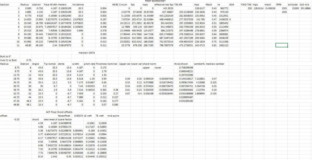
I can confirm this. Having done flight performance validation on the CL650, Felis 747, and flight model reworks on my own project, and the community C90 mod, the flight testing is the slowest bit. I have a workflow and template that I work from to test the effects of changes to the flight model. And omg the spread sheets: some images below. The props took me about a day to validate. I'll be publishing a new patch with the HSTAB airfoils and some other inclusions, right now im currently within 2% of POH climb and cruise performance, I have some more tweaking to do.
-
Elevator Trim Tab Animation reversed
CaptCrash replied to CaptCrash's topic in Mitsubishi Marquise MU-2 v2
@tkylerSame issue with the rudder trim. -
Elevator Trim Tab Animation reversed
CaptCrash replied to CaptCrash's topic in Mitsubishi Marquise MU-2 v2
@Ch.Cole summarizing the above, the trim tab applies forces primarily to the elevator to impart a deflection. -
Elevator Trim Tab Animation reversed
CaptCrash replied to CaptCrash's topic in Mitsubishi Marquise MU-2 v2
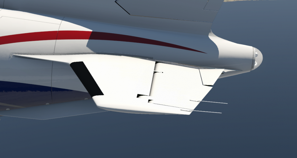
The elevator trim tab should move trailing edge down when nose up trim is applied and up when nose down trim is applied. It does this because the elevator is not mass nor aerodynamically balanced. This means the center of mass of the elevator is aft of the hinge line, the same is true of the trim tab. These two factors together mean the trim tab has to push up on the trailing edge of the elevator in a nose up trim situation and that can only be done by pushing down on the air flow. The opposite force is necessary for trim down. Often there is a secondary motion applied to the trim tab giving it a dual purpose, it can move in the direction of the trailing edge as the elevator is deflected, this an an anti-servo tab, to increase control loading and is common on planes with stabilators (flying horizontal stabs like on a piper archer). The tab movement can also move opposite the trailing edge direction to decrease control loading, this is called a servo tab), and is common in the configuration on the mu-2. https://www.boldmethod.com/learn-to-fly/systems/4-types-of-trim-tabs/ hope that answers you question -
With full nose up trim, the elevator trim deflects upwards but the trim afaik isn't an anti-servo tab
-
Would it be possible to split the wings up into Left and Right? That way there can be text on the wings? Sounds reasonable on the surface Crash. Don't see any reason why not. TK
-
Here is a tiled UDIM FBX with vertex paints applied for material ID. This file can be imported into surface painter and painted across UDIM tiles for a seamless painting workflow CPT_CRASH_MU2_Paintable_Areas_Exterior.fbx
-
Thanks! Ya i know how frustrating it can be. I'll keep an eye out for any other oddities, none so far though.
-
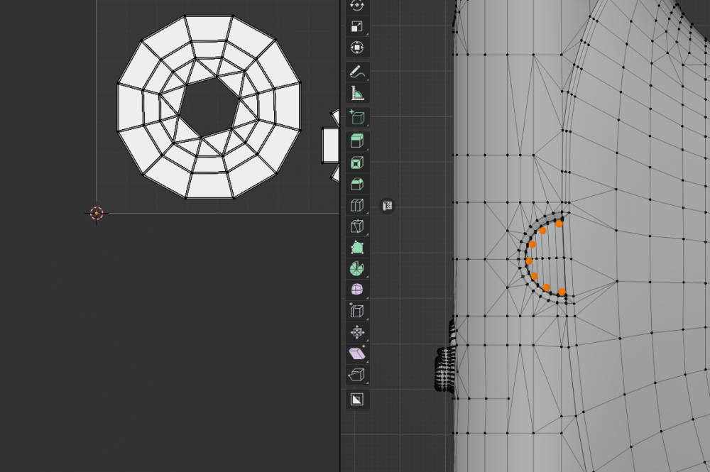
Hi Tom, There appears to be an error in the unwrap, the screws and some associated hardware on external3 are collapsed to 1 pixel making them unselectable in substance painter for uv mapping, the screw heads could probably be overlayed on the other one also in that image for the fwd and aft screw heads
-
After doing a review of the flight model and taking a fine chisel to it I was able to get the Performance more in line with the POH cruise figures. The take off performance seems better but has not been evaluated. This mod is NOT supported by TOGA Simulations. They are aware of it. TOGA Simulations are not obligated to offer any form of technical support to a modified aircraft, so don't contact them. IF YOU CHANGE YOUR ACF YOU ARE ON YOUR OWN. If you are not familiar with modifying the acf file with a text editor you will find this challenging but doable. You will find this very difficult to do if you aren't using notepad++. You will find this very easy if you use a file patching utility (https://www.google.com/search?&q=applying+diff+file+windows) or (https://www.google.com/search?q=applying+diff+file+mac). Things this mod does: 1) New wing airfoils 2) New Prop and prop airfoils 3) New max power 4) Tuned prop governor 5) cruise performance TAS within 1% of POH values 6) Take off behavior more aligned with POH takeoff profile 7) *NEW* Added ventral and wing tank fins Things this mod does NOT do: 1) alter fuel flows *NEEDS TOM* 2) modify the lua code 3) make the airplane easier to fly Things to do: 1) validate takeoff performance 2) validate climb performance 3) Tune EGT more, you will be at 660C at FL200 and cruise power *REQUIRES TOM* 4) Tune CG *DONE* 5) Validate OEI performance 6) validate airfoils xplane parameters (theres some nuanced values which dont affect normal regime flight dynamics but should be adjusted for correctness, these will become more important as stall behavior is validated) *DONE* 7) validate stall behavior - suspected flap aero is the issue, will probably require custom flap lift controller Things used to make this mod: 1) POH and AFM 2) Hartzell Aluminum Blade overhaul manual Things that were tested: 1) Climb and Cruise TAS at POH settings for 10k, FL200 at 11,500lbs, FL310 11,000lbs Instructions: 1) unzip the airfoils zip file into the following folder X-Plane 11\Aircraft\X-Aviation\Mitsubishi MU-2 Marquise v2\airfoils 2) BACK UP YOUR ORIGINAL ACF FILES. For those of you that want to use a patch file open the MU2_mod_unified.diff or the MU2_mod.diff and apply that patch file. MU2_mod_unified.diff is a context 0 unified diff file, the MU2_mod.diff is a WinMerg normal patch file. Proceed to step 4. 3) For the rest, I applaud your dedication, you will need to open the acf and manually modify the following (i highly recommend notepad++ for this) DO NOT under any circumstances use planemaker to make the changes. Plane maker converts all the values on file open then reconverts the values on file save which WILL induce uncontrolled file changes. The more times you open any file in planemaker and save it, the more changes get imparted. a) open the MU2_mod.diff file using notepad++ b) Each section is formatted in the following way [start line number],[end line number]c[start line number],[endlinenumber < old thing --- > new thing so for example 25621,25626c25621,25626 < P _wing/0/_Croot 0.500000000 < P _wing/0/_Ctip 0.583333313 < P _wing/0/_afl_file_R0 Clark-Y (good propeller).afl < P _wing/0/_afl_file_R1 Clark-Y (good propeller).afl < P _wing/0/_afl_file_T0 Clark-Y (good propeller).afl < P _wing/0/_afl_file_T1 Clark-Y (good propeller).afl --- > P _wing/0/_Croot 0.349166662 > P _wing/0/_Ctip 0.678333342 > P _wing/0/_afl_file_R0 NACA-2330.afl > P _wing/0/_afl_file_R1 NACA-2330.afl > P _wing/0/_afl_file_T0 NACA-0003.afl > P _wing/0/_afl_file_T1 NACA-0003.afl there was a change starting at line 25621 through lines 25626 the C means change. The change to be made are all the lines with ">" markers. c) manually replace all the values in the acf with the ">" values. excluding the ">" markers and replace so for example at line 25621 to 25626 your acf will look like this: P _wing/0/_Croot 0.500000000 P _wing/0/_Ctip 0.583333313 P _wing/0/_afl_file_R0 Clark-Y (good propeller).afl P _wing/0/_afl_file_R1 Clark-Y (good propeller).afl P _wing/0/_afl_file_T0 Clark-Y (good propeller).afl P _wing/0/_afl_file_T1 Clark-Y (good propeller).afl after modifying it should look like this: P _wing/0/_Croot 0.349166662 P _wing/0/_Ctip 0.678333342 P _wing/0/_afl_file_R0 NACA-2330.afl P _wing/0/_afl_file_R1 NACA-2330.afl P _wing/0/_afl_file_T0 NACA-0003.afl P _wing/0/_afl_file_T1 NACA-0003.afl 4) Save the file once all the changes have been applied. 5) In xplane adjust your prop lever axis response to go up to 100% per the image below I am very limited in time so I have done my best to explain the process, I highly suggest patching the file instead of manually editing. Enjoy. I will update things as they happen. I have very limited time to offer technical support (troubleshooting) for this, so I leave most of the trouble shooting as an exercise for the reader. Additionally the ods version of the W&B document doesnt contain the text labels that the excel version does (image of the excel version below) airfoils.zip MU2_mod_unified-2022-08-09.diff MU2_mod-2022-08-09.diff W&B.xlsx W&B.ods
-
With the turbine engines especially, they model of N2(throttle) -> N1 -> FF / EGT / oil press / Thrust, is challenging to work around because of the fixed N1 vs N2 relationship being insensitive to ANY atmospheric conditions including air density so I found I had to tune for takeoff or cruise but couldn't do both.
-
Did you check to make sure your axis are set up according to the documentation? In the documents folder is a file called Readme.txt Please take a look for the link to the documentation for setting up your control axis
-
Thanks for the quick response! I fully understand and empathize with your frustrations with the stock engine model. Having done some detailed mapping of the system for my own project I quickly came to the realization a that the stock engine model is functionally a single state function that can only be effectively tuned for takeoff or cruise performance in the case of the turbine part of the model. I look forward to seeing the updates!
-
Thanks for bringing the MU2 up to date! I really like the improvements. I have a couple areas of note: 1) After engine shutdown any subsequent ignition during start results in EGTs going immediately up to 700+C in less than 1 second while fuel flow behavior is consistent between starts, is this expected? If the engine necessitates a motor to reduce EGT would it be possible to implement an egt behavior that would indicate the engine is too hot to start? Additionally the subsequent restarts between engine 1 and 2 are not consistent. Engine 1 will have a max EGT of ~950C while engine 2 will remain at or below ~750C (video Below) EDIT: Additionally it appears that the EGT spike preceeds the fuel flow which thermodynamically doesnt seems to make much sense unless the sensors for the EGT are more responsive than those measuring fuel flow. 2) When pressing the unfeather buttons, the state of the condition levers change (Video below) the same occurs when using the engine stop switches. The unfeather switches cause the model animation to indicate movement aft, the stop switches indicate movement forward. I noticed this because I can set the hardware axis to bounce between two animation key frames which causes slight jittering in the animation and a constant update. Video order: Engine Start Video, control axis video
-
Forward slipping a transport category aircraft is not advised as an appropriate method for altitude loss. Non transport category aircraft may be able to do it, but, the emphasis in the transport category operational environment is on consistent and stabilized approach procedures that do not necessitate forward slips. If you find yourself in a position where a forward slip is necessary, that is considered an unstable approach and would mandate a go around.
- 1 reply
-
- 6
-

-

-
-
Yes, it is insufficient because there are crashes we have identified as being caused by other factor NOT involved in the stack trace, the full log assists in the identification of the state of the sim. Additionally we manually review every log to try and best ascertain why the sim crashed and provide useful troubleshooting steps for you to try as part of our dedication to supporting all users. Thank you so much for posting your log it will aid in the evaluation of your issue and subsequent analysis. Your cooperation is appreciated.
-
[LOGGED 2680] CTD When using VOR1 NAV mode
CaptCrash replied to AviationCode's topic in Crash To Desktop
Thank you! Can you provide the situation you were in? The post above gives instructions for the kind of information we need to collect to try and reproduce this issue on our end. -
Thanks @IAmJemmy I will note this and open up a ticket for the issue.
-
[NO RESPONSE] CTD: "tune->cont.name != ((void *)0)" failed
CaptCrash replied to Daffy's topic in Crash To Desktop
Are you still experiencing this crash in the latest version? -
Are you still experiencing crashes?


