Search the Community
Showing results for tags 'electrical system'.
-
Hi, While starting to use the TorqueSim BN-2 Islander v 1.2.1 for XP11 bought from X-Aviation, the electrical power to transponder, autopilot, adf receiver and chronometer lost suddenly. Tried XP-11 menu Flight > Edit failures > Fix all systems did not result in a solution. Only restarting the airplane. Anyone has a solution?
- 1 reply
-
- electrical system
- xp11
-
(and 1 more)
Tagged with:
-
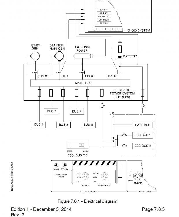
I'm looking for deeper understanding of the Crash Bar Lever. When on the ground and nothing else is connected to the electrical and following the checklist, you raise the crash bar. This has the effect of powering on the backup AHRS and G1000 display 1. The CAS message "BAT OFF" is displayed which means the main bus is powered by something other than the Battery. Question: Does raising the Crash Bar actually power an ESS BUS allowing the G1000 and AHRS to turn on? I see the next checklist item from the Daher manual is "ATIS COPIED". You wouldn't be able to do this if the G1000 and radios weren't connected. Can someone verify this for me? I've seen another TBM model for a flight simulator where raising the crash bar does nothing until you select batteries on, which I think is incorrect. Thanks
-
Hello all. This is my first post here and while I have the IXEG 737-300 installed, I am still doing ground school for a few hours, coming from the NG. I am studying in particular the electrical systems and AC and DC BUSSES and I am writing a studying guide. I have the probems that my data sources for the NG (BRADY, 2014, COJIN, 2015) tell me that : * in the NG ENG 1&2 START VALVEs are powered from 28V DC - BAT BUS (sect 1&2). - that's OK for engine #2, I tested it in the IXEG model. * ENGINE 1 & 2 RIGHT IGNITORS are powered from 115V AC STANDBY BUS - that's OK, I tested it in the IXEG model. While 1/ in my 737 NG simulation this assumptions looks correctly simulated and can be verified with experimental procedures (starting both engine only from BAT BUS and AC STANDBY is possible) 2/ I can in the classic IXEG start the engine #2 from BAT BUS and STANDBY AC BUS (with right igniter selected) and external bleed air source only. 3/ but I can't do the same for the left engine #1 ! BAT BUS and STBY AC BUS as sole AC and DC sources can't start engine #1. So I started playing with logic with electrical failures, standby power switch and transfer bus switch. I found out that in the IXEG model, while ENG 2 START VALVE is powered as usual from BAT BUS, ENG1 START VALVE would however be powered by AC XFER BUS 1. Because in the IXEG 737 restoring a experimentaly failed XFER BUS 1 with rstarter already in GRD position suddenly awakes the bleed air injection in engine #1. I am very astonished. Is it a bug or a very real difference with the 737 NG ? I was totally unable to find the complete wiring drawing including services for the classic. Best regards REFERENCES BRADY Chris, The Boeing 737 technical guide version 67. Tech Pilot Services Ltd : Frodsham, 2014 COJIN Ferdi, DE JONG Bert, B737Theory Manual : Boeing 737NG Systems. [En ligne] 2015.


