

gilbenl
-
Posts
162 -
Joined
-
Last visited
Content Type
Profiles
Forums
Latest X-Plane & Community News
Events
Downloads
Store
Everything posted by gilbenl
-
I suggest you reconsider how you did the wingbox. You cannot use the method I discussed in the tutorial only (I will finish it today), but its typically not a good idea to make the wingbox a solid block. It should be apart of the fuse.
-
You've gotta be doing something wrong, or omitting something. The backround image feature has been in blender forever, and its not something I would suspect for being buggy. What format did you convert your picture to?
-
Before you do that, I would suggest re-installing blender. Nevertheless, I suspect this is a result of user error, and not blender. Try creating a new file, open the backround image, even if it doesn't appear save the file and reopen blender.
-
First off, what version of Blender are you running? Assuming it's 2.48 or higher here are some things to keep in mind... 1) There is typically a delay between when you open the file, and when it pops up. Sometimes, it can take a minutes or two. 2) Check to see if you are possibly zoomed way in/out. If your zoomed way out, the image may be so small you cannot see it. 3) How many sectors in the view window are you working with (IE: Do you have sectors for the three orthos and a perspective, or is it just one big workspace)? -If you are working with multiple views, keep in mind that blender presents the same picture regardless of view. So, if you load the head on image while you're looking at the plane head on, then switch to the side view in the same window, it will still display the image loaded for that particular window. This wouldn't make it not appear, just something to keep in mind. 4) If the above doesn't help, post a picture with your workspace, and the backround image dialogue open, and figuring it out should be easy. I am making the assumption that you are using a backround image that is a standard file type (IE: .jpg, png, bmp, pdf, etc.) If not, then open the file in preview (or whatever program will allow you to open it, and save-as one of the aforementioned file types. This is just for rafael...these questions I will answer. The other one's...not so much. This is not an invite to start e-mailing me, just fyi. I am just answering this because it hasn't been mentioned yet, and it may benefit someone else as well.
-
Engine shape affects flight model.
-
Indi- You are my hero. ;D That is all.
-
Yeah...hello again Rafael. He was dumb enough to send me an e-mail to an address which is not disclosed to the public, but he knows from when I offered an answer to one of his questions...so it made finding out that xp9videos is really our good ole buddy the grade-D theif quite obvious. Why don't you just embrace your new title eh?
-
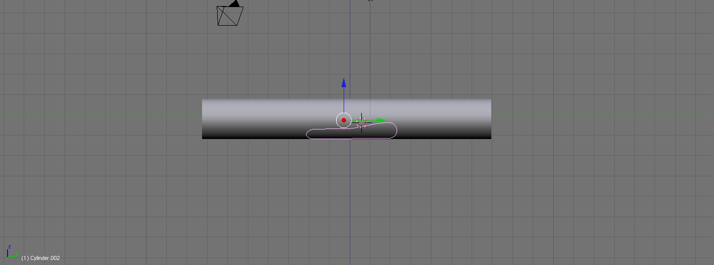
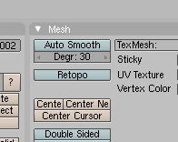
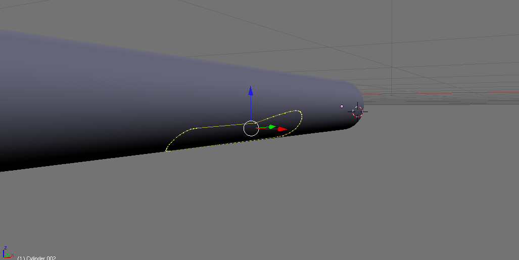
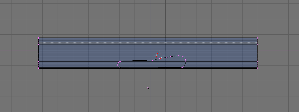
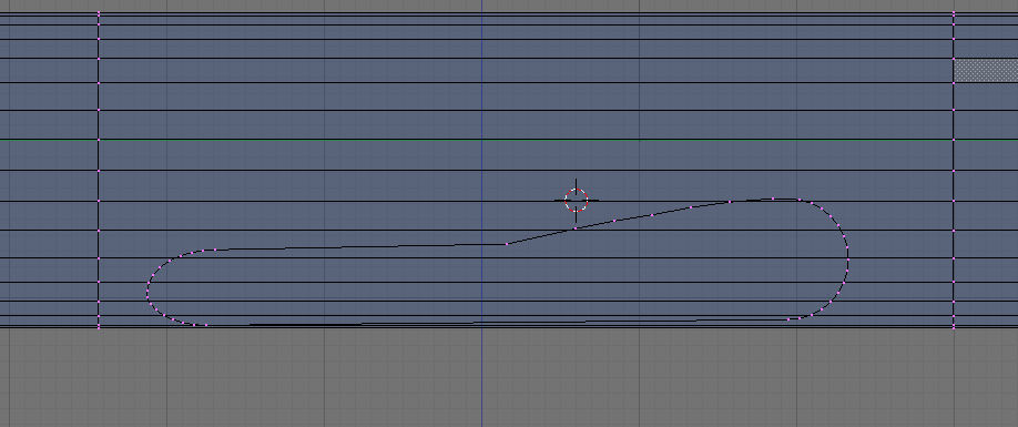
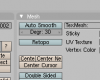
Hey all- I received a request to post a tutorial concerning how to build the wingbox on a obj fuselage. Like anything else, there are multiple ways to do this, and a number of nuances that will result in modifications to this procedure. So, take this as a basic guide, and be sure to critically analyze what your goal is. To begin, here we have a basic tube "fuse": You then switch to the side view (3), and create a separate object that is the outline of the wingbox root on the fuse. Note how many verticies you use for this, as you will need this number later. (makes things easier) Now, you go down to the menu on the bottom (in edit mode with the outline selected) and hit the retopo button. BE SURE TO BE LOOKING AT THE SIDE YOU WANT TO PROJECT THIS OUTLINE ON TO! Then, simply hit "G". The outline should snap to the contour of the fuse, and you'll get something like this: ***Before doing ANYTHING else, be sure to deselect the retopo button. Then, select the contoured outline and the fuse objects in object mode, and press ctrl-j to combine the objects. It should look like this: We then use the kinfe tool ("k") and create vertex loops at the boundaries of the wingbox outline, producing this: Next, erase the faces occupying the space inside of the outline, to make it look like this: This should be more than enough to occupy your time for now, and I'm tired, so this tutorial will be continued tomorrow...If you cannot wait, here are the rest of the steps w/o pictures: 8) Continue using the 'k' tool to create vertex loops for all of the verts on the top and bottom of the outline, so that the outline is now fully attached to the fuse. 9) At each end, strategically creat polys to join it to the original boundary vertex loops created in step 6. 10) Go to the side view again (3), and create another outline of the wing root, and space it appropriately in distance from the fuse. This outline should be composed of the same number of verts as the wingbox outline. 11) Strategically use the "k" tool to divide the new face loop into workable sections. For complicated curves in the wingbox (like on the 757), you should need 3-4 longitudinal loops. Less or more depending on the complexity of the curves. 12) Use ctrl-E-->edge slide to adjust their latitudinal position appropriately (left and right when looking from the nose back) 13) Contour/scale each longitudinal loop to create the appropriate contour and shape for your wingbox. ***Note: It's best to use/model only half a fuselage until after this step. Once complete, you can simply use the mirror modifier to duplicate this to the other side.


-
How about D-Grade theif?
-
Looking like some real quality work...keep it up!
-
Well, when I originally caught him stealing our engines, pylons, gear, wings, etc, I didn't have definitive proof it was also our fuse. These new "progress shots" are just further iterations of smooth and subsurf. I knew it was all ours to begin with, I just chose to give him the benefit of the doubt. What he did was he began by doing his "own fuse" then gave up and stole ours. In less than 5 minutes time, I was able to reproduce the IDENTICAL mesh that he showed on this site by applying the smooth feature precisely three times. I was even having a conversation with Cameron, the owner of this site, while I was doing this, and he has seen all the evidence. Furthermore, I have discussed it with the people who actually BUILT the fuse and they agree with my analysis. With all due respect, you have been swindled by the worst. Rafeal was banned from XPFW for doing this exact same thing with his "A300 project". The proof is there. Should you choose to ignore it, you'll go down with him. In private emails, I have given him countless warnings, and encouraged him to do his own work. He has once again proven to be a theif. PS: I will also be checking the 757 VC files and comparing them to the VC shots he has shown, because many of those objects look VERY familiar...IE the six sided switches, the PFD's and especially the gear handle.
-
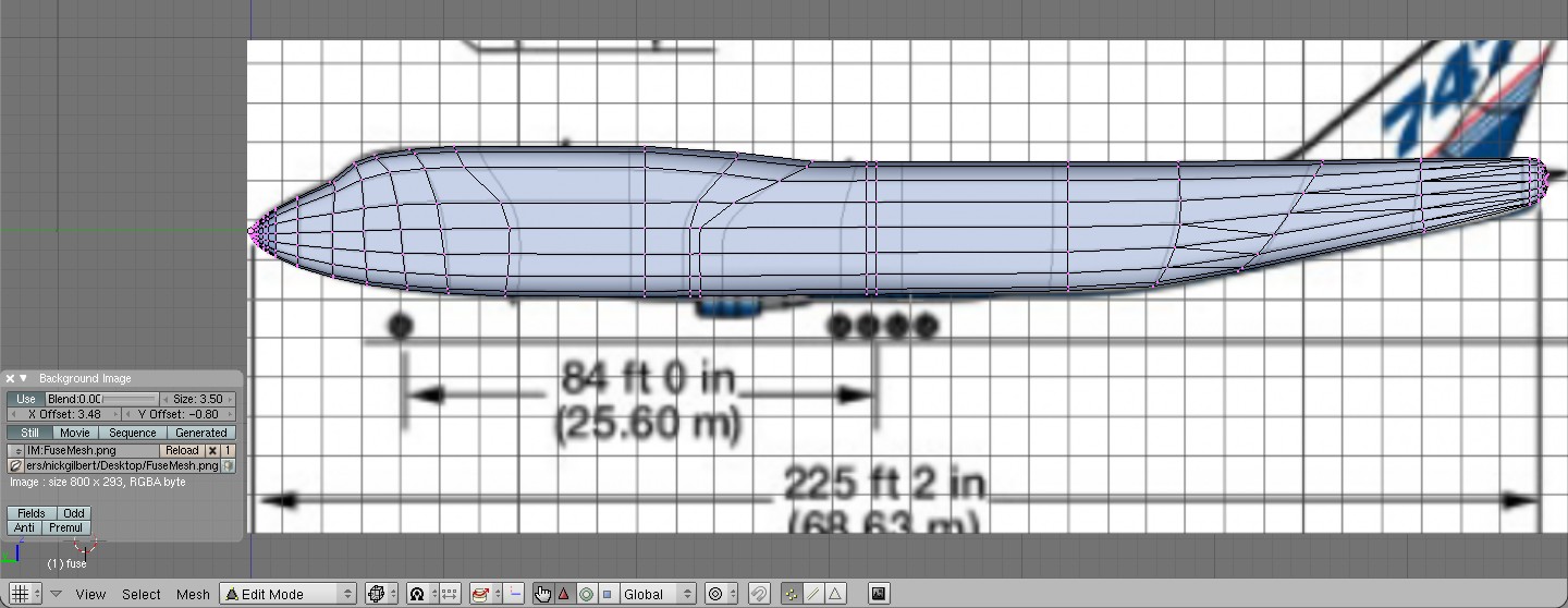
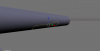
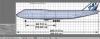
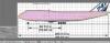
Hey Rafael- So, remember when I called you out on using XPFW's engines, pylons, gear, wings, and gear doors? You eventually admitted you used them, claiming they were only to show off where you were going. Well thats dishonest enough, but both X-Pilot and XPFW let it slide since you had not released it and you said they wouldn't be used....but you repeatedly told not only me, but everyone here that you had spent WEEKS working on the fuse. I had my suspicions, but I let it go... Well, after I saw these new pictures, and read your claim that your AMAZING fuse had 45,000 polys, I became suspicious. Here's why: The MD-80 fuse has about 3800 polys. Granted, its a smaller plane, but there's only one way to explain a 45,000 poly fuse: Extreme subsurf, or lying. Question is, if you had built your own fuse, why would you subsurf. Well, you managed to do both. Here's what you did. You took the XPFW 747 fuse obj, and you imported it into Blender or AC3D (whichever you use), and you got something that looked like this: That's our fuse, overlayed on your fuse/mesh preview you uploaded. Now that certainly doesn't raise any suspicion. But see, a faceted, rough fuse was not what you wanted, so you hit the smooth button EXACTLY 3 times, and now, VOILA! Now that looks mighty familiar don't it? All you had to do now was remove the extra vert here and there, straighten up some lines in sections that were erased from your early pictures (see the area under the V-Stab if anyone is curious), and you could then put out pics of something you thought you could convince people had taken you WEEKS of BRILLIANT work to complete. Unfortunately, you're a theif, a liar, and only in this for attention. My hands are shaking right now, and I feel sick to my stomach. In all my time involved in XP and 3D, I have NEVER ONCE run across someone who STOLE so much, and was caught SO many times. You just do not get it, do you? WE KNOW OUR WORK, AND WE KNOW WHEN SOMETHING IS STOLEN...Heck, I didn't even have a part in the original 744 build and this was extremely obvious. So, all said and done, you have wasted a month or so of your life on STEALING things. My god man, you could have built your own damn fuse in that time, and it would've looked a lot better than converting a fuse that's 3 years old and out-dated. What's worse is that you sucked someone else down with you! I bet Theo is going to LOVE you when he sees that he has been swindled. The good news is he didn't do anything wrong besides being tricked by you. You are one of the worst kind of thieves out there: You steal for nothing more than attention! When you do this, people develop hope and excitement...but inevitably, you get caught. Then, you not only hurt those you stole from, but all those who had faith and hope in what you do. You make me sick.

-
http://forums.x-pilot.com/index.php?topic=151.0 That's all you need.
-
Looks like you're off to a great start! Keep up the good work. If you have any questions, don't hesitate to ask!
-
I have always been on the side of the flight model being too twitchy, but there is something you should keep in mind: A joystick has no resistance, the control sweep is not always constant, and it always "snaps" back to center. In a real aircraft, there's no spring loading on the yoke to put it back to center. This is a fundemental problem with joysticks...their resistance is dependent upon the spring, and not the flight surfaces. If you try flying with a yoke, things are much, much better, but still nothing like the real thing. Basically, what you need is a way to add progressive resistance to the stick, without having it "snap" back to center. You may be saying "well, I don't release the stick" and that may help things, but in the end, you're still fighting a very sensitive input device that always wants to "snap" you back to center. When I get back home, I may try using a small clip to pre-compress the spring in the stick so that it won't make it snap back. This only compounds the issues Morten has raised, but even if all of his issues were addressed, the joystick would still make things seems "twitchy".
-
Rafael has a long history of "borrowing" things from other aircraft. This is why he is no longer welcome at XPFW. If you batch export the gear etc from our 744, and import the objects in AC3D, they're identical in every way. He didn't even bother to convert the triangles to quads. Everything you see, minus the fuse is IDENTICAL to our objects. Like I said, when you work on these planes for hours at a time (and I am only working on the update) you can pick out your objects from a mile a way. I really hate to see this though. The XP community needs people to learn how to build obj acf, and it really sucks to see people trying to cheat and steal others work just to gain some sort of unwarranted respect. You'll never learn anything if you don't do your own work and take baby steps. To the general public, there's nothing wrong with taking someone elses model and looking at the mesh etc. Heck, I do this ALL THE TIME. It's how you learn. That being said, this is only useful to see how its done. In my opinion the best part is the first model that took forever to build. It didn't come out perfect, but man, you did it. Each subsequent model will get better and better. Once you do this, then you will get the respect and credit you not only want, but deserve. I'll leave Rafael's thread to him now, but from here on out just to insure people don't get the wrong idea, I wouldn't use ANYTHING that's stolen, borrowed (whatever you want to call it). You don't use other people's work even to "show" where you're going. I won't say any more unless I see our stuff (or anyone else's I can prove). In those cases, you can bet I'll point out other's work. They did it, they deserve the credit.
-
Unfortunately, it would appear that we have an issue here. The landing gear, engine pylons, gear bay doors, and the wing sections that have magically appeared are property of XPFW; taken from our 744. This is highly frowned upon as all of you know, and we have contacted the author requesting that he either remove all property of XPFW from his plane, or face the consequences should he decide to release it to the public as-is. This is highly unfortunate as I know many of you were really looking forward to a new 747. That being said, XPFW is currently working on a major update of the 747, and I can assure you our new work will make up for the unethical behavior of this user. -Nick XPFW Team
-
Hey all- I had mentioned in my last post that my next tutorial would cover setting scale in Blender. Well, as I checked my facts, I came across the following link: http://homepage.ntlworld.com/r.burke2/precision_modelling1.html This clearly has all of the information one would ever need on this subject, as well as detailed instructions and examples on thier implementation. Therefore, I will simply pass on the link, and wait patiently for any specific questions y'all might have. Anyone who considers themselves (or strives to be) a "pro" level modeler should read the majority of this book because, quite frankly, XP is changing. No longer do "accurate-looking" models engender the praise they used to. Try measuring your work, and prepare to be dismayed. BUT FEAR NOT! If you do this FROM THE BEGINNING, it actually makes modeling MUCH easier (particularly with VC's) as it will take the guess work out of how big a knob should be. Where does one find such dimensions? Well, think outside of the box! There are groups of people who build full-size replica cockpits for home use, and they subsequently publish these dimensions in surprising detail. Here's just one example of the information that's out there: http://www.markuspilot.com/B737info/B737info.htm All those measurements just make me so happy! Now does this mean to have a good VC one must measure EVERYTHING? Heck no! In fact, with a few exceptions, this is down-right impossible. That being said, if you are able to get the measurements on a few items, you can scale and relate all other objects to the known. For example, all modern boeing panels (Comm, Nav, etc) are all 150 mm wide. That tiny detail can help immensely. How do you do that, you ask? Well, take the 737NG pedestal (pretend like you don't have the link above). You know that each "slot" for an item is 150mm wide, and you know that there are 3 columns of slots on the pedestal. 3X150=what class...450! Now, the pedestal is in fact 455mm wide, but once you build the sides, you'll end up with something about 453mm...THIS is close enough when you don't have explicit data. It's up to you what your margin of error is on this. I try not to be more than 5-10 mm off depending on the object, but so long as you're not INCHES off (25.4mm per inch, for us standard measure people), it is unlikely people will notice. Anyway, the point is, the data is out there. It's up to the intellect and SKILL of the author to extrapolate it, and come up with the appropriate dimensions. Enjoy the new bed time reading! -Nick
- 1 reply
-
- 1
-

-
Glad this tutorial has found an audience. My next tutorial should have been done before this, but it is none-the-less important: ESTABLISHING SCALE in Blender. The most disasterous thing that could happen to someone is you model an entire "thing" and you throw it in x-plane and it's the size of a shoe rather than a 747. If anyone has any specific processes they would like described, feel free to send me a PM. I check this site regularly, so if you do not receive a reply shortly, then it's either something I'm uninterested in doing, or is further down the list. -Nick
-
Incredible... :
-
Out of respect for Javier, let's not talk about any other aircraft round these parts m'kay? This is his show, and I don't think it's appropriate to try and steal the spotlight. I suggest we take the bashing and bragging alike elsewhere...Javier, back to you -Nick
-
I hate PC's...so Im prejudiced. That being said, if you go with the iMac, you're going to spend close to the cost of a new MacPro before you get an adequate graphics card (256MB or 512MB). If I were you, I would save up, and buy even the lowest end MacPro. This will allow you to progressively update the unit as your needs/funds permit. If you go the PC route, you'll get similar power for less money...but at the end of the day, its a PC *YUCK*. Also, keep in mind, if you are a student, you get a nice discount on Apple stuff ($200-300 USD depending on what you buy). Here is a system I would reccomend, should you go the mac route: http://store.apple.com/us/configure/MB871LL/A?mco=NDE4NDIwNA That's one baaad mamma jamma!
-
Learn something new everyday! Thanks for clearing things up Ben. Believe it or not, your blog was relatively understandable. Thanks boss!
-
Ben, as always, you know your stuff...but here's just a piece of anecdotal info: I will tell you that runnin XP immediately after a clean boot of the computer ALWAYS produces SIGNIFICANTLY higher FPS (30-50 FPS compared to 25-40), than running it following a long period of system up time. Dunno why, but its consistent. Whenever my FPS go to the crapper, a reboot will always bump 'em back up to a livable level. As for all of these "optimizers", believe it or not, the openGL one marginally improves things, but this may be a placebo effect. Aside from that, I would say all of these are just snake oil cure-alls that don't do diddly. One more note, and I am putting on my helmet before saying this BUT when I set settings of XP8 and XP9 to be the same, XP9 says it's using 85 MB of VRAM and XP8 says its using 120 MB of VRAM. With that in mind, XP8 runs faster while using more VRAM than XP9 does while it says it's using less...care to enlighten me? PS: this is minus shaders etc.
-
Well, first and foremost...how "low-end" are these computers? Also, do you plan to use all six to drive one sim, or do you plan to have 6 individual stations? Will this be a cockpit simulator, or just workstations with some joysticks? I will tell you this though, if you plan to use them all as individual stations, and have all the kids able to see the other planes on their system, its going to take some relatively powerful units to display 6 non-AI planes at one airport using XP's internal networking, as it presents the full aircraft, without any optimization (AFAIK). If you go with VATSIM or IVAO, and use their systems to present the other acf at the airport, you may be able to get away with lower end computers, but more detail is needed to recommend the best set-up. -Nick