

SchneiH2
-
Posts
137 -
Joined
-
Last visited
Content Type
Profiles
Forums
Latest X-Plane & Community News
Events
Downloads
Store
Everything posted by SchneiH2
-
Is there really nobody who can help? Where is my plane (on the map)? The first snapshot shows a XP default plane, the second the situation with my plane. Thank you and best regards SHJ
-
Hi everybody I have designed a new plane from scratch which does not display a plane icon on the XP flight map. Can somebody explain why and how to correct. Thanks and regards SHJ


-
Hi Jim Thank you for the response. I will report this accordingly. Bes regards SHJ
-
Hi everybody I am currently working on the electrical system of my plane (SSJ100) and came accross a problem with the GPU. For switching the GPU I use a command (sim/electrical/GPU_toggle). However, when checking the corresponding dataref sim/cockpit2/annunciators/external_power_on it does not change the value. When checking the standard instruments in PlaneMaker I could aslo not find a button/switch for the GPU (just for checking). Thank you up-front for possible help. Best regards SHJ
-
Generic instruments, problem with NAV1 indicator
SchneiH2 replied to SchneiH2's topic in Aircraft Development
Hi Jim That's it! Many, many thanks for your help and patience! Best regards SHJ -
Generic instruments, problem with NAV1 indicator
SchneiH2 replied to SchneiH2's topic in Aircraft Development
Hi Jim A short feedback on some progress: Except NAV1 (ILS) everything now works fine. I could not find a basic mistake, however, what I did is to build the indicators again from scratch in the 2D-panel of PlaneMaker. After having tested the 2D-panel I copied them to the 3D-panel where everything seems to work fine. To my surprise this approach (building from scratch) did not work if I did it directly in the 3D-panel of PlaneMaker. The situation with the NAV1 remains strange. If I tune NAV1 to a VOR it works fine but as soon if I tune it to an ILS frequency it does not work (although there is a correct indication in the default EFIS means there is a signal). Is there perhaps some setting missing in my setup of XPlane10? By the way, i have tested it with a 'standard' plane of XPlane10 (B747 NASA) with the same result. Best regards SHJ -
Generic instruments, problem with NAV1 indicator
SchneiH2 replied to SchneiH2's topic in Aircraft Development
Hi Jim Thanks for the quick response. Yes, the MFD is the default instrument. That's why I am so puzzled. I will countercheck again all setup of the generic instrument (NAV1 indicator) etc. and let you know. Thank you again and best regards SHJ -
Generic instruments, problem with NAV1 indicator
SchneiH2 replied to SchneiH2's topic in Aircraft Development
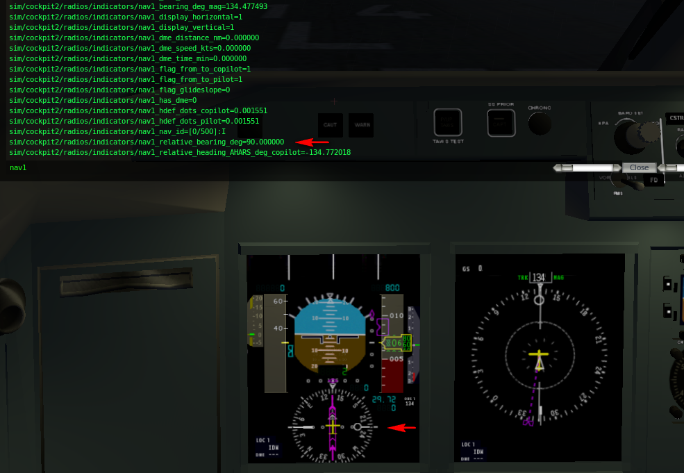
Hi Jim Thank you very much for your reply. In fact this also my understanding of 'relative bearing'. The second screenshot shows a situation where the NAV1 IS tuned to the ILS (please refer to the HSI on PFD) and on the MFD rose the NAV1 pointer shows the correct direction (same direction as ILS indicator, screenshot was made when plane is positioned on that runway). This is exactly the point where I got stuck, i.e. that on the MFD the NAV1 pointer indication is absolutely correct. Do you have any idea in which direction I should investigate this matter further? Thank you nad best regards SHJ -
Generic instruments, problem with NAV1 indicator
SchneiH2 replied to SchneiH2's topic in Aircraft Development
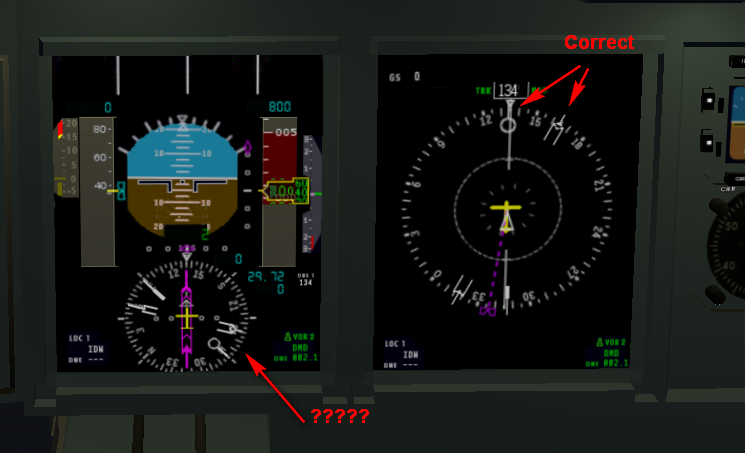
Hi Jim Thank you for your response. Unfortunately, this does not work either. However, I think I came a bit closer to the problem. The indication of the bearing itself is obviously correct (absolute value. see also attached pic). Means to absolute coordinates with 0 degrees at 12 o'clock. The 'wrong' thing is that it is not in relation to the current indication of the HSI rose. There is no difference in the behaviour if I use sim/cockpit2/radios/indicators/nav1_relative_bearing_deg or sim/cockpit2/radios/indicators/nav1_bearing_deg. Perhaps you could look again into this matter and give some idea. Thank you and best regards SHJ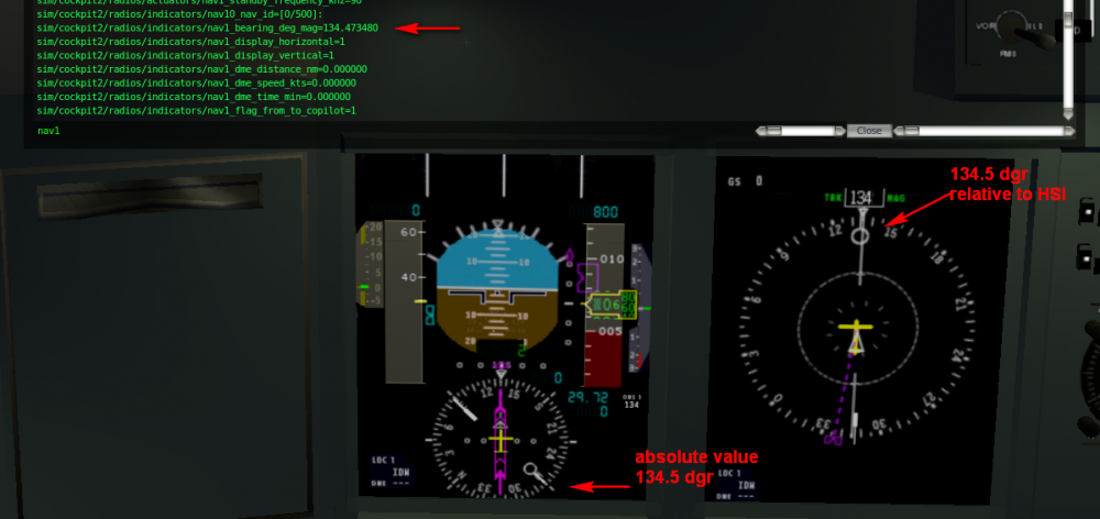
-
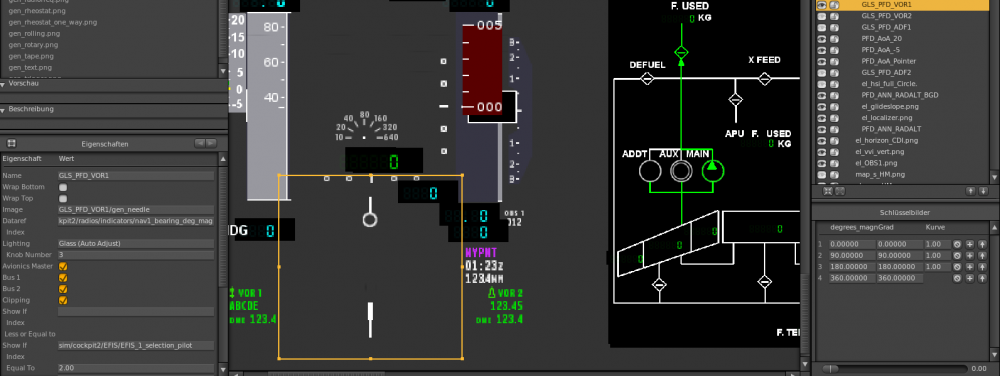
Hi everybody I came across another issue with generic instrumens/datarefs which seems to me very strange. I have added to the standard HSI on the PFD 4 generic needles for NAV1, NAV2, ADF1 and ADF2. As dataref for the NAV’s I use sim/cockpit2/radios/indicators/nav1 (2)_bearing_deg_ mag. However, the indication in XPlane is obviously ‘wrong’, i.e. if I take the indication from the standard EFIS (which is indeed correct) as benchmark the generic needles show some strange heading bug. To my understanding the configuration of the generic needles in PlaneMaker is correct. Frankly speaking I have no clue what might be wrong Thank you very much up-front and best regards SHJ
-
Question on instruments (EFIS airspeed indicator)
SchneiH2 replied to SchneiH2's topic in Aircraft Development
Hi Jim Just to give a feedback and to close the topic - the point was that I did not understand correctly the functionality of the 'generic pointer', in particular that the second picture (the 'background', not the pointer itself) must be resized in a corresponding image editing tool to define the display (clipping) area. The mistake I made was to try to resize the original backgound picture which is just a small bar in PlaneMaker. This indeed leads to the distortion as described above. Thank you again for your help which finally put me on the right track. Best regards SHJ -
Question on instruments (EFIS airspeed indicator)
SchneiH2 replied to SchneiH2's topic in Aircraft Development
Hi Jim Sorry for a possible misunderstanding. However, if I look to your pics I see on the properties tab the option 'vertical/horizontal' and 'offset' which I cannot find when using a generic tape. To my understanding they belong to a generic pointer. However, when using a generic tape as basis and adding the your speed tape png (as shown in attached pic) itis not animated at all. On the contrary, just the normal tape function works in the background. Best regards SHJ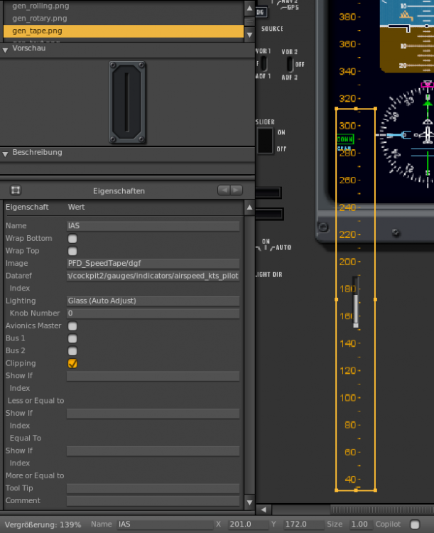
-
Question on instruments (EFIS airspeed indicator)
SchneiH2 replied to SchneiH2's topic in Aircraft Development
Hi Jim Thank you very much for your comprehensive response. If I got it correctly you used as basic generic instrument a 'generic pointer'. This was also my idea and basically this works fine until I start to resize the window/area of the instrument and use the clipping option. This completely distorts the image for the speed tape. For better understanding I have attached two images. Perhaps you could give a hint what I am doing wrong. Thank you and best regards SHJ

-
Question on instruments (EFIS airspeed indicator)
SchneiH2 replied to SchneiH2's topic in Aircraft Development
Hi JIm Thank you for your post. Indeed, I have tried to find an appropriate generic instrument for this purpose. To my understanding there are two which might be suitable for my needs - generic pointer and generic tape. However, so far I could not get a satisfying result. The generic pointer seems not to be a very elegant solution since I have to use a static picture for the whole speed tape. But the real problem is that when selecting the 'clipping' option in PlaneMaker to avoid that the (long, long) speed tape exceeds the boundaries of the instrument and resizing the instrument afterwards leads to a complete distortion of the speed tape picture. The problem with the generic tape is that my current knowledge allows me only to animate an expanding bar. However, the control also contains a number block which I do not know how to address and/or tu use (if ever possible). Perhaps you or somebody else could give some more advice. Thank you very much and best regards SHJ -
Question on instruments (EFIS airspeed indicator)
SchneiH2 replied to SchneiH2's topic in Aircraft Development
Hi everybody Is there nobody out there who can help me on this topic? Hope the description is clear enough, otherwise please let me know. Best regards SHJ -
Question on instruments (EFIS airspeed indicator)
SchneiH2 replied to SchneiH2's topic in Aircraft Development
One small correction of my post - it is meant the airspeed indicator on the PFD! Sorry for possible confusion. Best regards SHJ -
Hi everybody For the plane I am working on (SSJ 100) I need to modify the EFIS airspeed indicator. The airspeed indicator of this plane just shows an airspeed strip w/o a magnifier window for the current airspeed. Therefore, I need to solve two issues: Eliminating of the magnifier window for the current airspeed => done by editing the corresponding PNGs of the standard instrument. Enlarging the numbers displayed on the airspeed strip The latter turned out to be quite tricky (at least for me) since just enlarging the instrument itself in PlaneMaker does not solve the problem as the EFIS area is quite stuffed and proportions shall be considered. I was wondering if a generic instrument might be used, however, I could not identify such. Having checked the structure of the standard airspeed indicator I noticed that in respect of the airspeed strip it consists basically of a background picture, a number block including tickmarks and a txt-file with some configuration information. In the number block PNG there are 4 lines of numbers (0-9) whereat two lines are of bigger size compared to the other two. Is it possible to somehow (desirably w/o script programming) address the large numbers contained in this number block or to generally edit the number size for the airspeed strip? Thank you very much up-front and best regards SHJ
-
Hi Just to give a short feedback and to close this topic (temporarily?). I have noticed that I did not correctly understand/use the Blender animation, i.e. I have used just one keyframe for animation. Indeed, at least to my understanding, an animation consist at least of 2 keyframes and the corresponding datarefs shall have two different values. Having changed this indeed the light can now be directed accordingly. The transformation of coordinates is still tricky also in relation of the cone size/effect. Needs still some work. So far many thanks for your replies. Hope to can count on your help further! Best regards SHJ
-
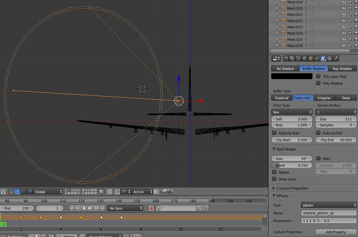
Hi Jim, hi airfighter Thank you very much for your responses. Having looked at the content under the shown link in the post from airfighter I am not completely sure if there is some explanation to my specific issue. The point is that I believe to have understood the necessity of normalization of coordinates (dx, dy, dz) as long as these parameters are part of the particular parametric light. The light type I am using does not having them: airplane_generic_sp R G B INDEX SIZE W (versus e.g. airplane_strobe_sp R G B INDEX SIZE X Y Z W). To my understanding this is exactly what is being referred to under the mentioned section in the developer guide (‘All lights are modified by OBJ animation, so one way to modify the direction of the light is to put it inside an animation and use a rotation. Thus you can use an OBJ animation to ‘aim’ a light that does not have parameters for direction.'’). I was trying to upload the OBJ-file but got an error message that I m not permitted to upload this kind of file. Can you advice how to proceed with this. Thank you very much and best regards SHJ
-
Hi everybody I am currently working on the lights for an aircraft based on parametrized lights (reference: http://developer.x-plane.com/?article=airplane-parameterized-light-guide). Can anybody provide some help on the description under section 'Directionality of Lights' especially in terms of the last part. I am trying to create a (directional with some cone) generic_light_sp for a tail illumination, i.e. the direction must be mainly in vertical direction with some inclination towards the tail. According to my understanding of the coordinate system for lights this will be -y direction with some +/- x component. As this type of light does not have direction parameters I have been trying to 'modify the direction of lights putting them inside an animation'. However, so far without much success. The workflow I am using is the following: - adding a spot light in Blender (to have a direction indication) - defining the light and adding the paramters - rotating the spot in the necessary direction with consideration of the necessary translation of coordinates, i.e. for a vertical direction the cone of the spot in Blender must be directed along the Global positive y coordinate. - once in the final position I just assign a Rotation-keyframe to the light. However, it seems that I do not achieve the desired effect, i.e. the direction does not change. By changing the cone size the illuminated area changes, however, it seems that light axis always directs to the front o the plane. Would be great to get some help. Best regards SHJ

-
Hi Jim Thank you very much for the correct hint. Indeed, having changed the settings to internal lighting for the cockpit object in Plane Maker solved the problem. Best regards SHJ
-
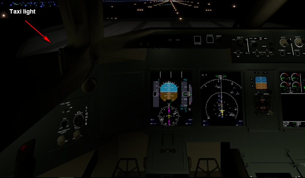
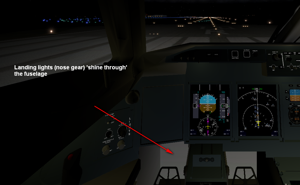
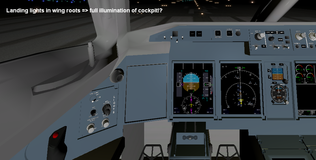
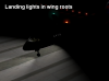
Hi everybody First of all I would like to wish all forum members a very Happy New Year! I am currently working on the aircraft lights and came accross a problem with the landing lights. I use a prameterized (landing) light which basically works fine, however, it creates a strange effect in XP10 as shown in attached screen captures. It seems that the landing light 'shines through' the fuselage. Placing the landing lights in the wing roots leads to afull illumination of the cockpit as if they were shining through the cabin. Is there something I am doing wrong? Thank you for possible help and best regards SHJ
-
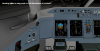
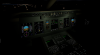
Dear Jim Finally, I did it thanks to your help. Indeed, I obviously missed one parameter, I have also noticed that the last parameter (width of cone) obviously must have the value 1. However, this is just the first attempt without playing around with the parameters respectively finetuning them. For interested forum members attached are two screen captures (seetings + result) Thanks again and best regards SHJ

-
Dear Jim Thank you very much for your response. I will check and let you know. Best regards SHJ
-
Dear JIm Thank you for your response. However, I am not sure whether it is related to the cockpit light problem as I use for the switch a simple toggle manipulator. I have mentioned the drag_axis_pix-manipulator in my previous post just to 'proove' that I use XP10 and it works fine (thanks to your earlier explanation on this subject). I am still stuck with the light problem. Best regards SHJ